Arduino UNO R3
⚡ The essentials in 60 seconds
- mcu — Microchip (ex-Atmel) ATmega328P, 8-bit AVR core, 16 MHz ceramic resonator (IC supports up to 20 MHz @ 5 V). ATmega328P product page
- memory — 32 KB flash (0.5 KB used by bootloader), 2 KB SRAM, 1 KB EEPROM (Wikipedia; EEPROM also highlighted on the board page).
- gpu_storage — none (MCU board, no OS-level graphics or filesystem; external SPI SD via shields).
- i_o — 14 digital I/O, 6 PWM (pins 3, 5, 6, 9, 10, 11), 6 analog inputs (10-bit ADC), 1× UART, 1× SPI, 1× I²C (Wikipedia). I²C on A4/A5 (SDA/SCL also broken out next to AREF — R3 header addition).
- usb — USB-B connector; serial over USB handled by an ATmega16U2 running USB-to-serial firmware (ATmega8U2 on R1/R2) — no FTDI chip (Wikipedia, store page).
- power — USB, or 5.5/2.1 mm barrel jack accepting 6–20 V (7–12 V recommended), protected by a series diode; VIN pin has no reverse protection. Outputs: 5 V and 3.3 V (3.3 V pin limited to 50 mA). Per-pin DC current: Wikipedia Uno page lists 20 mA; older Arduino datasheets stated 40 mA.
- On this board : 9 tutorials · 10 code
The Arduino Uno R3 stands as the definitive entry point into the world of electronics and physical computing, a status earned through its widespread adoption, extensive documentation, and robust community support. As the third hardware revision of the original Uno series, which was initially developed and released by the Arduino company in 2010, the R3 represents a mature iteration of a board that has become synonymous with the maker movement. While the exact year of the R3 revision is often cited as 2012, it is important to note that this specific date remains unverified in certain technical sources, though the board itself remains active and is still sold on the official store as the default first board for new users. The board’s enduring popularity is not merely a matter of nostalgia; it is driven by its role as the reference standard for the entire ecosystem. The physical form factor and pin layout of the Uno R3 established the "shield" standard, a modular expansion system that allows hundreds of add-on boards to plug directly into the main unit, creating a vast library of compatible hardware that spans from simple LED drivers to complex motor controllers.
At the heart of the Uno R3 is the Microchip ATmega328P, an 8-bit AVR microcontroller that runs at a clock speed of 16 MHz. To understand what this means for a beginner, imagine the clock speed as the tempo of a musician; at 16 million cycles per second, the microcontroller can perform basic instructions very quickly, though it is not designed for heavy computational tasks like video processing or complex artificial intelligence. The chip supports up to 20 MHz at 5 volts, but the board is configured for 16 MHz using a ceramic resonator, a component that provides a stable timing reference. The memory architecture is modest but sufficient for learning and prototyping: it includes 32 KB of flash memory for storing your program (with 0.5 KB reserved for the bootloader), 2 KB of SRAM for temporary data processing, and 1 KB of EEPROM for storing small amounts of data that must survive when the power is turned off. There is no operating system or graphical processing unit; the code runs directly on the hardware, a concept known as bare-metal programming, which allows for precise control over timing and resources.
The input and output capabilities of the Uno R3 are designed to bridge the gap between digital logic and the analog physical world. The board features 14 digital I/O pins, six of which support Pulse Width Modulation (PWM). PWM is a technique that simulates an analog output using a digital pin by rapidly switching the voltage on and off; by varying the ratio of on-time to off-time, you can control the brightness of an LED or the speed of a motor without needing a dedicated analog output pin. Additionally, there are six analog inputs capable of reading continuous voltage levels with 10-bit resolution, meaning they can distinguish between 1024 different voltage steps. Communication with other devices is handled via standard protocols: one UART for serial communication, one SPI bus for high-speed data transfer, and one I2C bus for connecting sensors and displays. Notably, the R3 revision introduced specific header changes, including dedicated pins for I2C (SDA and SCL) next to the AREF pin and an IOREF pin, which have become critical for ensuring compatibility with newer shields.
Power management is a critical aspect of using the Uno R3 safely. The board can be powered via a USB connection or through a barrel jack that accepts a voltage range of 6 to 20 volts, with 7 to 12 volts being the recommended range. This wide input range is managed by a linear voltage regulator, which steps down the higher input voltage to the 5 volts needed by the microcontroller and peripherals. Because linear regulators dissipate excess energy as heat, feeding the board with voltages near the upper limit of 20 volts can cause the regulator to become quite hot, a physical characteristic users should be aware of. It is crucial to note that the VIN pin, which allows direct access to the input voltage, lacks reverse polarity protection. While the barrel jack has a series diode to protect against incorrect polarity, connecting a power source to VIN with reversed polarity can permanently damage the board. The board also provides 3.3-volt and 5-volt outputs for external components, though the 3.3-volt pin is limited to 50 milliamps of current.
Connectivity and programming are handled through a USB-B connector, which serves both as the power source and the communication link to a computer. Unlike older revisions that used an FTDI chip, the R3 uses an ATmega16U2 microcontroller to handle the USB-to-serial conversion. This chip runs its own firmware and can be reflashed by the user via a Device Firmware Upgrade (DFU) mode, offering greater flexibility and speed than previous designs. However, this complexity introduces a known quirk: when a computer opens the serial port, the board automatically resets. This is a feature designed to allow the bootloader to accept new code, but it can cause the loss of the first few characters of data sent immediately after connection, a behavior that beginners often mistake for a bug. Programming is typically done using the Arduino IDE, which compiles C/C++ code into a format the AVR chip understands, though tools like PlatformIO and arduino-cli are also supported.
Despite its robustness, the Uno R3 has limitations that users must understand. The per-pin current limit is a subject of some ambiguity; while older datasheets suggested 40 mA, current documentation and community consensus advise designing for a conservative 20 mA per pin to ensure reliability and prevent damage to the microcontroller. Furthermore, the market is flooded with third-party compatible boards. While these clones are often cheaper, they may use different voltage regulators or USB-to-UART chips, which can alter driver behavior and safety margins. The original Uno R3 remains the safest bet for compatibility and support, especially given that it is still actively sold and supported. For those looking to expand their skills, the board supports real-time operating systems like FreeRTOS and can be controlled from a computer using the Firmata protocol, allowing for high-level scripting in languages like Python. Whether you are blinking an LED, reading a sensor, or controlling a robot, the Arduino Uno R3 provides a stable, well-documented foundation that continues to serve as the primary learning tool for millions of hobbyists and professionals worldwide.

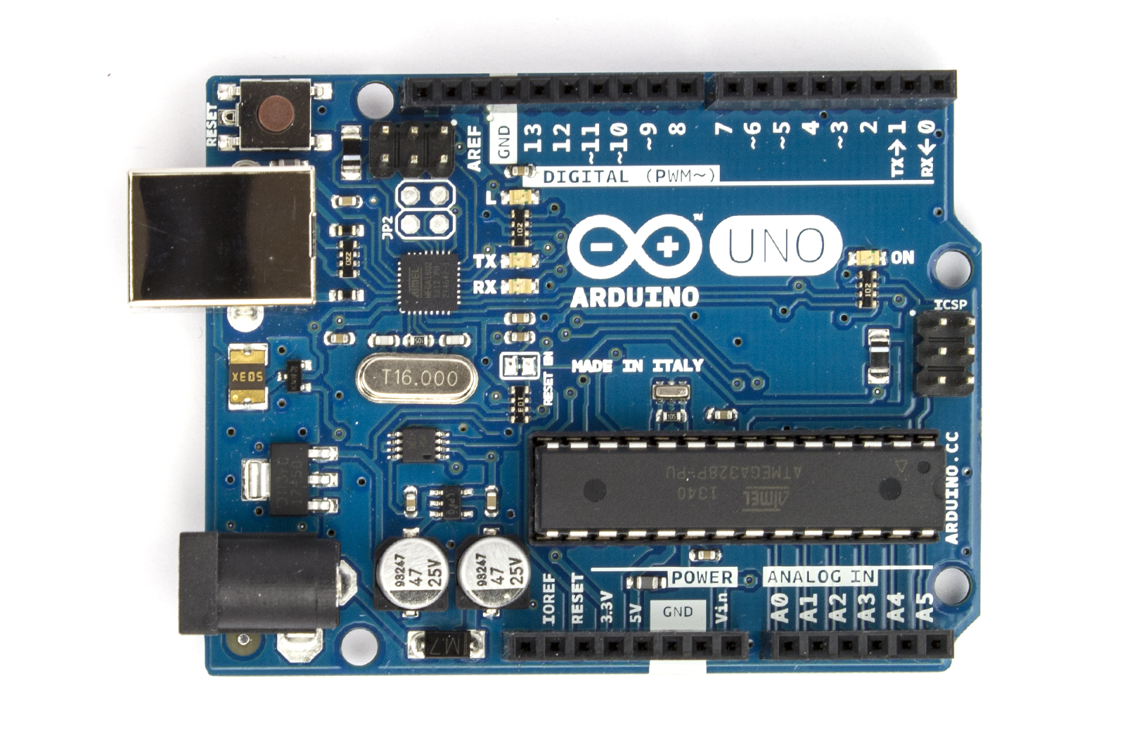
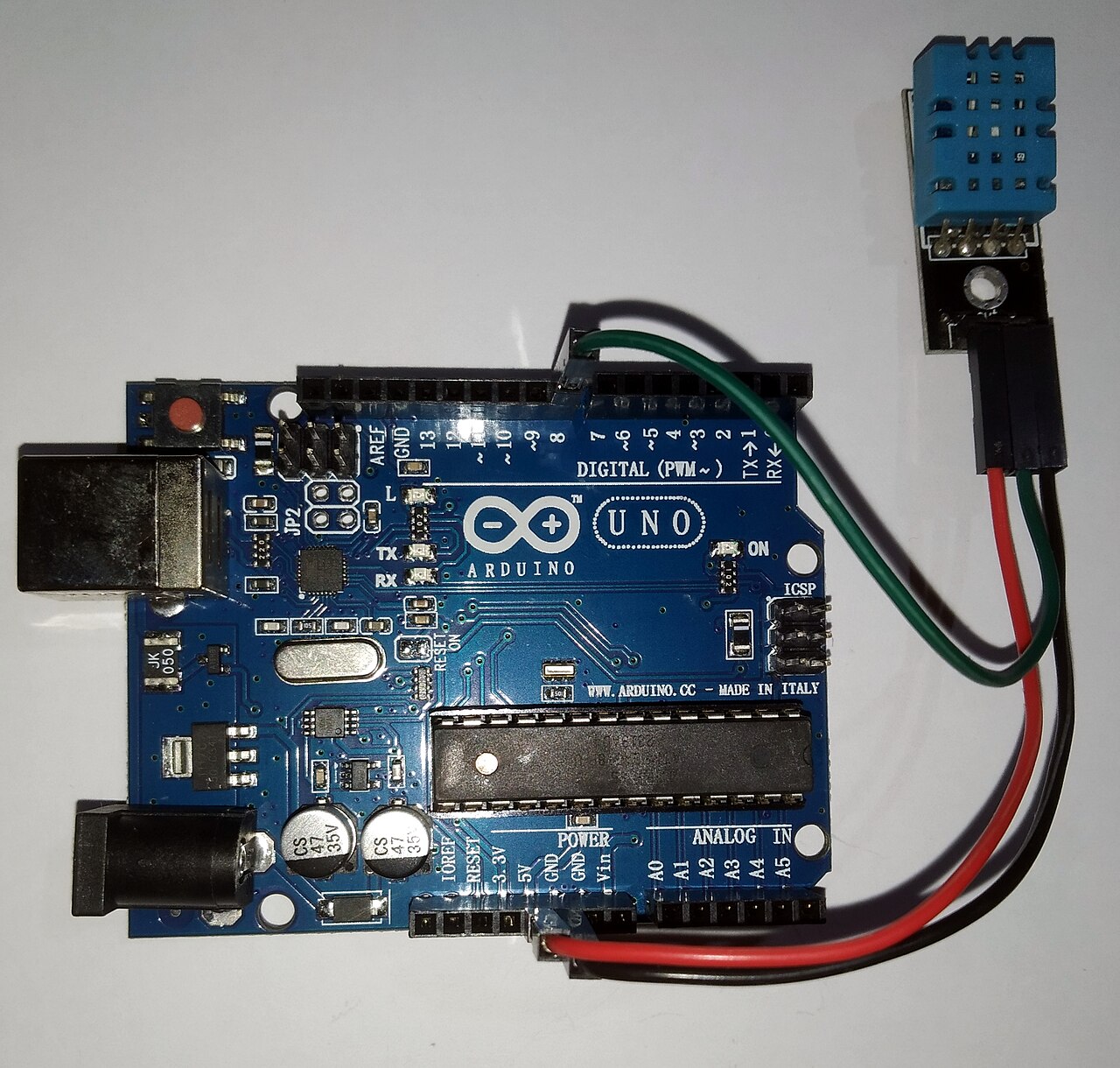
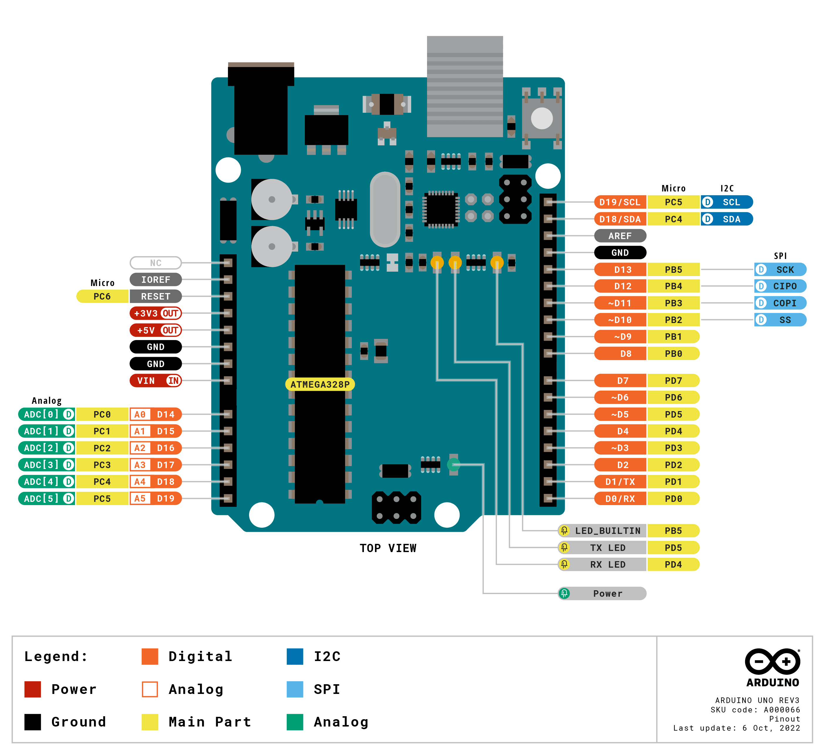
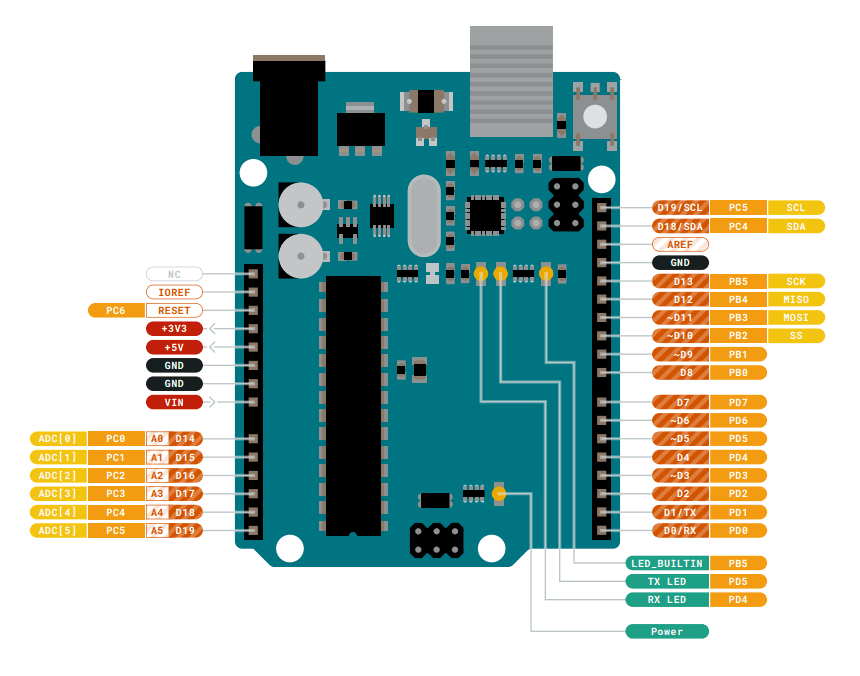
Pinout diagram
| Attr | Specs | verified |
|---|---|---|
mcu | Microchip (ex-Atmel) ATmega328P, 8-bit AVR core, 16 MHz ceramic resonator (IC supports up to 20 MHz @ 5 V). ATmega328P product page | ✔ |
memory | 32 KB flash (0.5 KB used by bootloader), 2 KB SRAM, 1 KB EEPROM (Wikipedia; EEPROM also highlighted on the board page). | ✔ |
gpu_storage | none (MCU board, no OS-level graphics or filesystem; external SPI SD via shields). | ? unverified |
i_o | 14 digital I/O, 6 PWM (pins 3, 5, 6, 9, 10, 11), 6 analog inputs (10-bit ADC), 1× UART, 1× SPI, 1× I²C (Wikipedia). I²C on A4/A5 (SDA/SCL also broken out next to AREF — R3 header addition). | ✔ |
usb | USB-B connector; serial over USB handled by an ATmega16U2 running USB-to-serial firmware (ATmega8U2 on R1/R2) — no FTDI chip (Wikipedia, store page). | ✔ |
power | USB, or 5.5/2.1 mm barrel jack accepting 6–20 V (7–12 V recommended), protected by a series diode; VIN pin has no reverse protection. Outputs: 5 V and 3.3 V (3.3 V pin limited to 50 mA). Per-pin DC current: Wikipedia Uno page lists 20 mA; older Arduino datasheets stated 40 mA. | ? unverified |
size_weight | 68.6 × 53.4 mm, 25 g (Wikipedia). | ✔ |
- Manufacturer: Arduino (arduino.cc / Arduino AG). The Uno series was "initially developed and released by the Arduino company in 2010"; the R3 is the third hardware revision of the Uno. (Wikipedia — Arduino Uno)
- Year: Uno series 2010 (Wikipedia).
- Status: Active — still sold on the official store (Arduino Store — UNO Rev3) and still the default "first board" of the family (docs.arduino.cc/hardware/uno-rev3).
- Launch price:
- Variants: UNO R3 through-hole (A000066) and UNO R3 SMD; sold as "Genuino UNO" outside the US during 2015–2016 (Wikipedia — Arduino); successors UNO R4 Minima and UNO R4 WiFi (June 2023, Wikipedia); plus a huge ecosystem of third-party compatible boards (often with different regulators/USB chips, Wikipedia — Arduino Nano, comparison note).
+ Strengths
- The reference board of the ecosystem — "the most used and documented board of the whole Arduino family" (board page); the shield form factor it standardized is used by hundreds of add-ons.
- Replaceable DIP MCU: the ATmega328P sits in a socket — "worst case scenario you can replace the chip for a few dollars and start over again" (board page).
- R3 header additions (SDA/SCL next to AREF, IOREF, 3.3 V) that became the Uno shield standard, carried forward unchanged into the R4 family (store R4 page).
- 16U2-based USB (faster and more flexible than the FTDI designs it replaced; user-reflashable over DFU) (store page).
- Barrel jack + VIN for battery/adapter operation independent of USB (board page).
− Weaknesses
- Older R1/R2 boards use the ATmega8U2, a different USB chip with its own DFU recovery procedure; botching that reflash can make the USB port invisible until fixed via DFU mode (store page).
- Heat from the linear regulator when fed near the input limits: input range 6–20 V but only 7–12 V recommended — dropping large differentials across the 5 V LDO heats the board (Wikipedia — Arduino Uno).
- VIN has no reverse protection (only the barrel jack has the series diode); injecting power into VIN without an external diode can damage the board (Wikipedia).
- Auto-reset DTR quirk: opening the serial port resets the board and the bootloader "will intercept the first few bytes of data sent to the board after a connection is opened" — classic cause of lost first characters in serial protocols (Wikipedia — Arduino Nano, "Automatic (software) reset", same AVR design family).
- Clones vary: third-party Uno boards "often have a different voltage regulator / different USB-to-UART chip / different solder mask", changing driver behavior and absolute maxima (Wikipedia — Arduino Nano comparison note).
- Per-pin current spec ambiguity (20 mA vs 40 mA) — see
- Retour d'expérience expert expert — expert-arduino
- Salut a tous. Je reviens sur l'Uno R3, toujours la carte de reference malgre l'arrivee des R4. Le grand avantage reste le MCU ATmega328P en socket : si vous cramez la puce, vous la remplacez pour quelques euros sans changer toute la carte. Attention toutefois a deux pieges recents. D'abord, la conn… — expert-arduino
- Merci pour ce rappel sur la chauffe du regulateur. J'ai justement un souci avec des clones achetes pas chers. Sur ma carte officielle, tout va bien, mais sur mes trois clones, j'ai des problèmes de drivers USB qui sautent. Est-ce que c'est lie au fait qu'ils n'utilisent pas forcement le même chip U… — maker-debutant
- Exactement, maker-debutant. Les clones utilisent souvent un autre chip USB-to-UART ou un regulateur different. Si les drivers sautent, verifiez si votre clone utilise un CH340 ou un FTDI au lieu du 16U2, car les drivers ne sont pas les mêmes. Pour le reset DTR, si tu perds les premiers caractères, … — expert-arduino
Community feedback and projects
- My news and weather scroller project forum.arduino.cc
- Connecting a Laser Distance Sensor to Arduino UNO – My Setup & Example Code forum.arduino.cc
- Arduino UNO R3 and ESP8266 node mcu connection keeps having a problem with the communication forum.arduino.cc
- Boardotron - hard to find support forum.arduino.cc
- A000066-datasheet.pdf datasheet
- Older R1/R2 boards use the ATmega8U2, a different USB chip with its own DFU recovery procedure; botching that reflash can make the USB port invisible until fixed via DFU mode (store page).
- Heat from the linear regulator when fed near the input limits: input range 6–20 V but only 7–12 V recommended — dropping large differentials across the 5 V LDO heats the board (Wikipedia — Arduino Uno).
- VIN has no reverse protection (only the barrel jack has the series diode); injecting power into VIN without an external diode can damage the board (Wikipedia).
- Auto-reset DTR quirk: opening the serial port resets the board and the bootloader "will intercept the first few bytes of data sent to the board after a connection is opened" — classic cause of lost first characters in serial protocols (Wikipedia — Arduino Nano, "Automatic (software) reset", same AVR design family).
- Clones vary: third-party Uno boards "often have a different voltage regulator / different USB-to-UART chip / different solder mask", changing driver behavior and absolute maxima (Wikipedia — Arduino Nano comparison note).
- Per-pin current spec ambiguity (20 mA vs 40 mA) — see
- Faire clignoter la LED intégrée de l'UNO R3 debutant Schéma : IMG-uno-r3-debutant-1-clignoter-led-uno.svg — Arduino UNO R3 vue de dessus, flèche sur la LED marquée L (pin 13) et câble USB-B branché.
- Allumer une LED avec un bouton poussoir debutant Schéma : IMG-uno-r3-debutant-2-bouton-poussoir-led.svg — UNO R3 sur breadboard : bouton entre la pin 2 et GND, LED + 330 Ω entre la pin 13 et GND.
- Faire varier la luminosité avec un potentiomètre (ADC + PWM) debutant Schéma : IMG-uno-r3-debutant-3-potentiometre-fade-pwm.svg — potentiomètre 10 kΩ dont le curseur va sur A0, LED + 330 Ω sur la pin PWM 9.
- Thermomètre de lumière : LDR, seuils et hystérésis intermediaire Schéma : IMG-uno-r3-intermediaire-1-capteur-lumiere-ldr.svg — pont diviseur LDR + résistance 10 kΩ entre 5 V et GND, point milieu vers A1, LED témoin sur pin 12.
- Télémétrie série robuste vers le Traceur série intermediaire Schéma : IMG-uno-r3-intermediaire-2-telemetrie-serie-robuste.svg — UNO R3 reliée en USB à un PC, écran affichant des courbes (Traceur série), annotation du quirk DTR de réinitialisation.
- Multitâche non bloquant : heartbeat + bouton avec debounce intermediaire Schéma : IMG-uno-r3-intermediaire-3-multitache-millis-debounce.svg — UNO R3 avec bouton sur pin 2 vers GND et LED sur pin 13, horloge dessinée symbolisant millis().
- Data logger sur EEPROM : persistance sans usure avance Schéma : IMG-uno-r3-avance-1-datalogger-eeprom.svg — UNO R3 avec LDR sur A1, puce ATmega328P en évidence avec la mention EEPROM 1 Ko, bouton de sauvegarde sur pin 2.
- Scanner le bus I²C de l'UNO (A4/A5) avance Schéma : IMG-uno-r3-avance-2-scanner-bus-i2c.svg — UNO R3 avec un module I²C (afficheur OLED) sur le bus A4 (SDA) / A5 (SCL), pull-up R1/R2 notées, broches SDA/SCL près de AREF mises en évidence.
- Réparer une UNO muette : 16U2, DFU et programmation ICSP avance Schéma : IMG-uno-r3-avance-3-recuperation-usb-16u2-icsp.svg — UNO R3 avec zoom sur le connecteur ICSP 2×3 broches et la puce ATmega16U2, jump RESET-ATMEGA16U2, câble ISP entre deux cartes.
Code library — examples written for this board
clignotante.inoArduinobouton-poussoir.inoArduinopwm-fade.inoArduinocapteur-lumiere-ldr.inoArduinoservo-balayage.inoArduinoruban-neopixel.inoArduinocapteur-dht11.inoArduinocommande-serie.inoArduinoecran-i2c-lcd.inoArduinobuzzer-melodie.inoArduino
Examples and repos found online
- arduino/ArduinoCore-avr github.com
- arduino-libraries/Servo github.com
- arduino-libraries/SD github.com
- arduino-libraries/LiquidCrystal github.com
- gmostofabd/Arduino-Examples-with-Proteus-Simulations github.com