Arduino Pro Mini
⚡ The essentials in 60 seconds
- mcu — Atmel (now Microchip) ATmega328P (early boards: ATmega168) — 8-bit AVR RISC core, modified Harvard architecture, ~1 MIPS/MHz, max 20 MHz (Wikipedia — ATmega328). No GPU, no FPU, no USB hardware in the chip (Wikipedia — ATmega328: "USB interface: No").
- clock — 16 MHz (5 V version) or 8 MHz (3.3 V version) ceramic resonator on board ("on-board resonator", Arduino retired page; f_cpu=16000000L / 8000000L in boards.txt).
- memory — 32 kB flash (0.5 kB used by the bootloader per the official page — note the shipped ATmegaBOOT actually reserves 2 kB, see Systems), 2 kB SRAM, 1 kB EEPROM (Arduino retired page).
- digital_i_o — 14 pins (D2–D13 on one edge, D0/D1 on the other), of which 6 PWM (3, 5, 6, 9, 10, 11, 8-bit via analogWrite). Each pin max 40 mA, internal pull-ups 20–50 kΩ, I/O level = 3.3 V or 5 V depending on model (Arduino retired page).
- analog — 10-bit ADC. The official page's intro says "6 analog inputs"; its Input/Output section says the board exposes 8 ADC channels with "four of them … on the headers on the edge of the board; two (inputs 4 and 5) on holes in the interior of the board" — ADC6/ADC7 are broken out on the latest SparkFun revision ("We've broken out ADC6 and ADC7", SparkFun page). The ATmega328 offers 6 ADC channels in DIP-28, 8 in TQFP/QFN (Wikipedia — ATmega328).
- comms — 1× UART (pins 0 RX / 1 TX, wired to the 6-pin programming header), 1× SPI (10 SS, 11 MOSI, 12 MISO, 13 SCK), 1× I²C/TWI (A4 SDA / A5 SCL); SoftwareSerial works on any digital pin (Arduino retired page).
- On this board : 9 tutorials · 10 code
The Arduino Pro Mini stands as a testament to minimalist engineering, designed not for the ease of a breadboard prototype but for the permanence of embedded installation. Originally conceived and manufactured by SparkFun Electronics, this board represents a pivotal moment in the evolution of the Arduino ecosystem, where the focus shifted from convenient development to efficient deployment. Unlike its larger siblings, such as the Arduino Uno, the Pro Mini strips away the bulky USB interface and the standard pin headers, resulting in a compact form factor intended to be soldered directly into a final project. This design philosophy prioritizes space and cost efficiency, making it a favorite among hobbyists and professionals who need to integrate microcontroller logic into tight spaces, such as inside a wearable device, a custom remote control, or a permanent home automation node. The board is built around the Atmel ATmega328P microcontroller, an 8-bit AVR RISC processor that has become the de facto standard for many Arduino projects due to its balance of performance and power efficiency. While the chip itself is capable of running at speeds up to 20 MHz, the Pro Mini is typically configured to run at either 16 MHz with a 5-volt supply or 8 MHz with a 3.3-volt supply. This dual-variant approach allows users to choose between raw processing speed, suitable for driving faster peripherals, and lower power consumption, which is critical for battery-operated devices. It is important to note that the 3.3-volt version is not merely a voltage regulator adjustment; the lower clock speed ensures the microcontroller operates within its safe electrical limits, preventing damage to the silicon.
Programming the Pro Mini requires a different mindset than using boards with built-in USB ports. Because the board lacks a dedicated USB-to-serial converter chip, it cannot be connected directly to a computer via a USB cable. Instead, communication and power are handled through a six-pin header on the edge of the board. This header is designed to interface with an external USB-to-Serial adapter, most commonly an FTDI cable or a SparkFun FTDI Basic breakout board. This separation of concerns means that the adapter is only needed during the development and debugging phase. Once the code is uploaded and the board is programmed, the adapter can be removed, leaving only the microcontroller and its necessary power connections. This significantly reduces the idle power consumption of the final product, as the power-hungry USB interface is no longer drawing current. The six-pin header carries the necessary signals for serial communication, including transmit and receive lines, as well as a reset line. This reset line is connected to the microcontroller’s reset pin through a small capacitor, which enables an auto-reset feature. When the serial port is opened by the Arduino IDE, this circuit momentarily pulls the reset line low, restarting the microcontroller and putting it into bootloader mode, ready to accept new code. This feature streamlines the workflow, allowing users to simply click "Upload" in the software without manually pressing a button on the board. However, this convenience comes with a caveat: if you use a generic USB-to-Serial adapter that does not expose the DTR (Data Terminal Ready) signal, or if you use an FTDI cable that lacks this specific wiring, the auto-reset will not function. In such cases, you must manually press the reset button on the board just as the upload process begins, a small but frequent source of frustration for newcomers.
The physical layout of the Pro Mini is designed for flexibility in permanent installations. The board comes without pre-soldered headers, offering users the choice to solder male headers for breadboard compatibility, female headers for stacking, or simply solder wires directly to the pads for a low-profile fit. The digital input/output pins are arranged along the edges, with fourteen digital pins available, six of which support Pulse Width Modulation (PWM). PWM is a technique that allows the microcontroller to simulate analog output by rapidly switching a digital pin on and off, which is useful for controlling motor speeds or LED brightness. The board also provides analog inputs, with the latest revisions exposing up to eight channels, although only four are typically accessible on the main edge headers, while the others may require soldering to internal pads. This abundance of analog channels is beneficial for sensor-heavy applications. The board’s power management is equally flexible. It can be powered by a regulated 5-volt or 3.3-volt supply connected to the VCC pin, or by an unregulated voltage up to 12 volts fed into the RAW pin. The RAW pin connects to an on-board linear voltage regulator, which steps down the higher voltage to the level required by the microcontroller. While this is convenient for connecting to battery packs or wall adapters, it is important to understand that linear regulators dissipate excess voltage as heat. Therefore, powering a 5-volt board from a 12-volt source will generate noticeable warmth, especially if the board is drawing significant current. For battery-powered projects, this inefficiency can drain power quickly, making direct regulated supply to the VCC pin a more efficient choice if the battery voltage is already within the acceptable range.
Despite its retirement from the official Arduino store, the Pro Mini remains a vibrant part of the maker community, largely due to its open-source design and the widespread availability of compatible clones. The board’s simplicity has made it a target for replication, resulting in a market flooded with third-party versions. While these clones offer affordability, they can vary significantly in quality. Some may use ceramic resonators instead of more precise quartz crystals, leading to slight timing inaccuracies that can affect serial communication speeds. Others might have inconsistent fuse settings, which are the low-level configuration bits that tell the microcontroller how to boot and what clock source to use. A common pitfall for users is selecting the wrong board profile in the Arduino IDE. Choosing the 5-volt/16 MHz profile for a 3.3-volt/8 MHz board, or vice versa, will result in upload errors because the bootloader expects a different communication speed and timing. Additionally, the factory bootloader on older boards reserves a significant portion of the flash memory, limiting the size of the sketches you can upload. Many enthusiasts choose to replace this with a more optimized bootloader called Optiboot, which is smaller and faster, freeing up more memory for user code and enabling higher upload speeds. This customization highlights the Pro Mini’s role not just as a component, but as a platform for learning the deeper intricacies of microcontroller programming and hardware modification. Whether used for a simple blinking LED or a complex wireless sensor network, the Arduino Pro Mini remains a powerful tool for those willing to engage with the hardware at a fundamental level, offering a direct connection to the silicon that drives modern electronics.

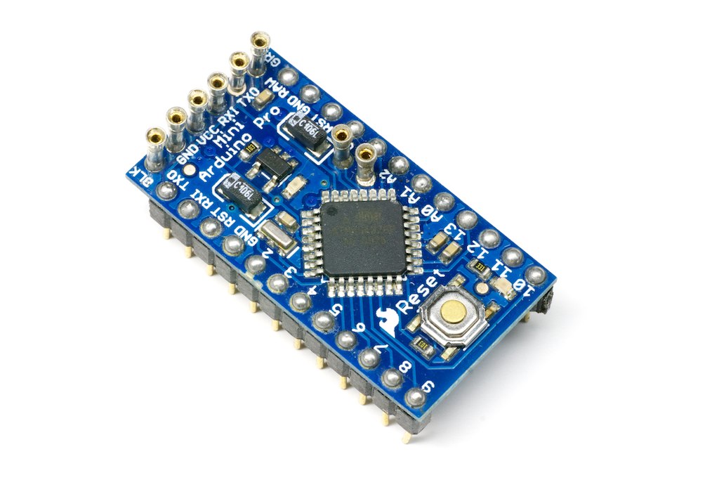
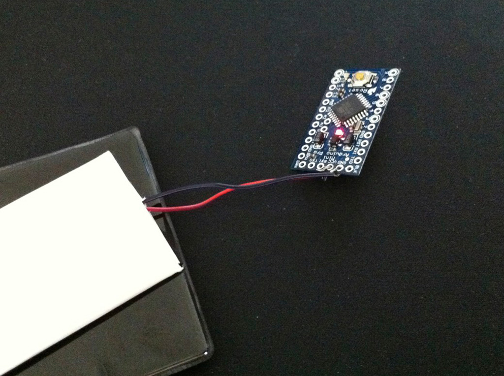
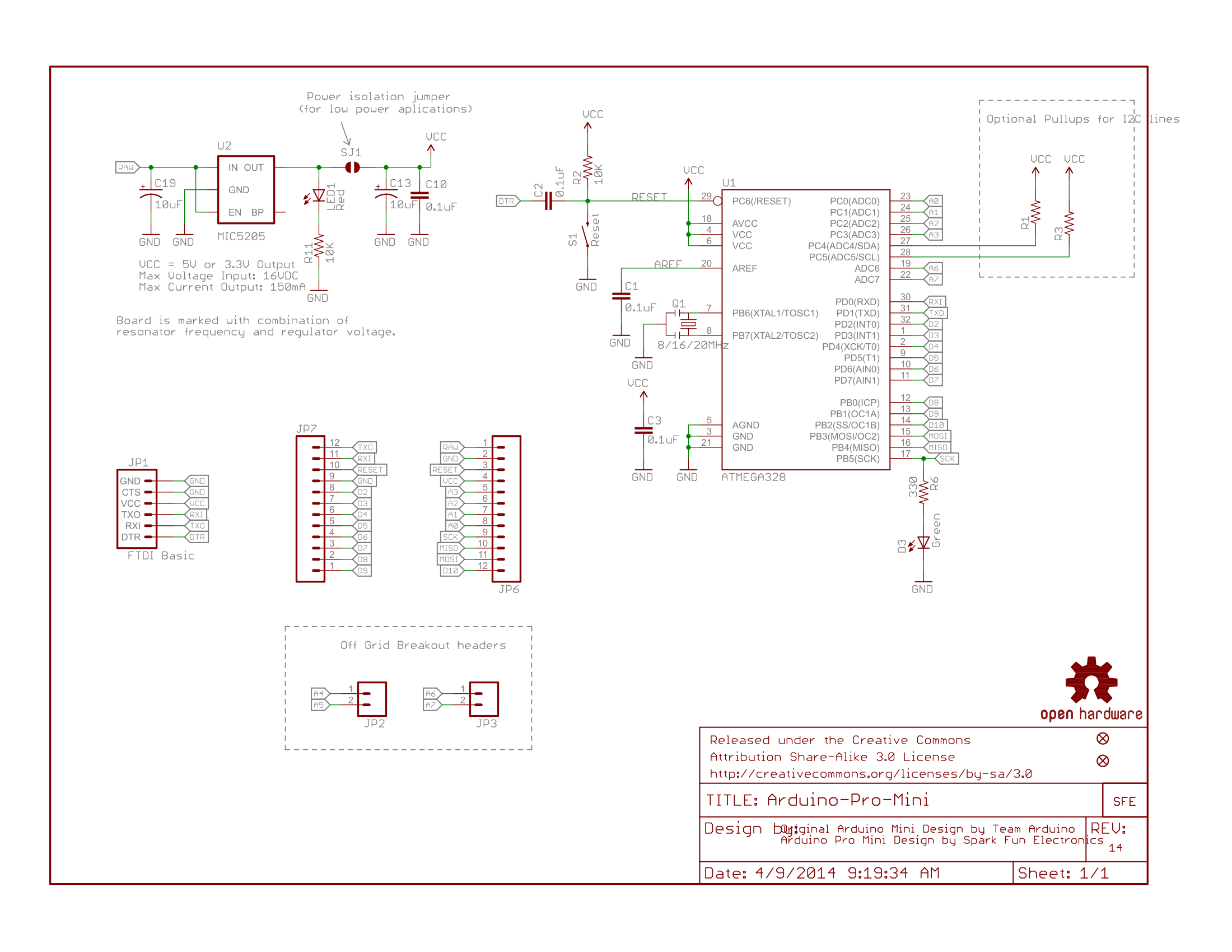
Pinout diagram
| Attr | Specs | verified |
|---|---|---|
mcu | Atmel (now Microchip) ATmega328P (early boards: ATmega168) — 8-bit AVR RISC core, modified Harvard architecture, ~1 MIPS/MHz, max 20 MHz (Wikipedia — ATmega328). No GPU, no FPU, no USB hardware in the chip (Wikipedia — ATmega328: "USB interface: No"). | ✔ |
clock | 16 MHz (5 V version) or 8 MHz (3.3 V version) ceramic resonator on board ("on-board resonator", Arduino retired page; f_cpu=16000000L / 8000000L in boards.txt). | ✔ |
memory | 32 kB flash (0.5 kB used by the bootloader per the official page — note the shipped ATmegaBOOT actually reserves 2 kB, see Systems), 2 kB SRAM, 1 kB EEPROM (Arduino retired page). | ✔ |
digital_i_o | 14 pins (D2–D13 on one edge, D0/D1 on the other), of which 6 PWM (3, 5, 6, 9, 10, 11, 8-bit via analogWrite). Each pin max 40 mA, internal pull-ups 20–50 kΩ, I/O level = 3.3 V or 5 V depending on model (Arduino retired page). | ✔ |
analog | 10-bit ADC. The official page's intro says "6 analog inputs"; its Input/Output section says the board exposes 8 ADC channels with "four of them … on the headers on the edge of the board; two (inputs 4 and 5) on holes in the interior of the board" — ADC6/ADC7 are broken out on the latest SparkFun revision ("We've broken out ADC6 and ADC7", SparkFun page). The ATmega328 offers 6 ADC channels in DIP-28, 8 in TQFP/QFN (Wikipedia — ATmega328). | ✔ |
comms | 1× UART (pins 0 RX / 1 TX, wired to the 6-pin programming header), 1× SPI (10 SS, 11 MOSI, 12 MISO, 13 SCK), 1× I²C/TWI (A4 SDA / A5 SCL); SoftwareSerial works on any digital pin (Arduino retired page). | ✔ |
usb | none — no USB chip at all. Programming and USB serial go through the 6-pin header (GND, CTS?, VCC, RXI, TO, GND layout with DTR/RTS on the outer column) designed for an FTDI cable or Sparkfun FTDI Basic breakout ("A six pin header can be connected to an FTDI cable or Sparkfun breakout board to provide USB power and communication to the board", Arduino retired page). | ✔ |
other_pins | Reset (bring LOW to reset), built-in LED on D13, reset button, mounting holes; headers not pre-soldered (Arduino retired page). | ✔ |
power | regulated 3.3 V or 5 V into VCC, or unregulated up to 12 VDC into RAW through the on-board linear regulator; or 5 V via the FTDI cable/breakout (Arduino retired page, SparkFun page). | ✔ |
- Manufacturer: SparkFun Electronics — "The Arduino Pro Mini was designed and is manufactured by SparkFun Electronics" (Arduino retired board page, page content last updated 2024-03-14 per the site's git metadata); sold under the Arduino brand (SKU E000025) and still sold by SparkFun (SparkFun product page).
- Year: Introduced by SparkFun circa 2008–2009.
- Status: Retired/EOL at Arduino — it lives in the "Retired boards" section of the official docs (retired board page) and the Arduino store URL store.arduino.cc/products/arduino-pro-mini returns 404 (fetched 2026-10-13). Still sold by SparkFun (5 V/16 MHz page live 2026-10-13; "a portion of every sale is given back to Arduino LLC"). The design remains open hardware, and countless clones are sold worldwide.
- Launch price:
- Variants (all in the official platform definition, ArduinoCore-avr boards.txt, fetched 2026-10-13, board pro = "Arduino Pro or Pro Mini"): - ATmega328P, 5 V, 16 MHz (pro16MHzatmega328) — the classic version. - ATmega328P, 3.3 V, 8 MHz (pro8MHzatmega328). - ATmega168, 5 V, 16 MHz (pro16MHzatmega168) and ATmega168, 3.3 V, 8 MHz (pro8MHzatmega168) — early production chips. - "There are two version of the Pro Mini. One runs at 3.3V and 8 MHz, the other at 5V and 16 MHz" (Arduino retired board page).
+ Strengths
- Smallest classic AVR Arduino, built for permanent installs: "intended for semi-permanent installation in objects or exhibitions… comes without pre-mounted headers, allowing the use of various types of connectors or direct soldering of wires" (Arduino retired page).
- No USB chip = tiny, cheap, low idle power: "To keep the board as small as possible, we removed the USB circuitry" (SparkFun page); the FTDI adapter only exists while programming.
- Two system voltages from one design: 5 V/16 MHz for Uno-level speed and 3.3 V/8 MHz for battery/3.3 V-peripheral designs; logic level always equals VCC (Arduino retired page).
- Pin layout compatible with the Arduino Mini (Arduino retired page).
- Extra analog channels: latest revision breaks out ADC6/ADC7 (beyond the Uno's 6 channels) and adds footprints for optional I²C pull-up resistors (SparkFun page).
- Flexible power input: RAW ≤ 12 VDC via on-board regulator, direct regulated VCC, or FTDI 5 V (Arduino retired page).
- De-facto standard for embedded AVR builds: the ATmega328 "is commonly used… on the popular Arduino development platform, namely the Arduino Uno, Arduino Pro Mini and Arduino Nano models" (Wikipedia — ATmega328).
− Weaknesses
- Wrong board selection = classic upload failure. Selecting the 5 V/16 MHz entry for a 3.3 V/8 MHz board (or an Optiboot-equipped board while "old bootloader" 57600 speed is assumed) produces avrdude: stk500_getsync … not in sync: resp=0x00 / programmer is not responding — the most common Pro Mini support request (forum thread 1364138, forum thread 1410388, forum thread 1180127).
- RX/TX swap trap: the FTDI Basic mates directly and works, but hand-wiring a USB-UART adapter (CP2102, another Arduino) requires crossing TX↔RX; forgetting it yields the same not in sync errors (forum thread 1364138).
- *FTDI cable has no DTR → no auto-reset:* "the FTDI cable does not bring out the DTR pin so the auto-reset feature will not work" — you must press reset just before upload (SparkFun Pro page).
- Internal-RC-oscillator serial drift on the 3.3 V/8 MHz ATmega168 fuse set: "problems with serial on 3.3V Pro Minis when using the internal 8 MHz RC oscillator, but solved it by recalibrating the oscillator" via OSCCAL (forum thread 1154615); the fuse evidence is low_fuses=0xc6 for pro.menu.cpu.8MHzatmega168 (boards.txt).
- Brown-out surprises on fresh 3.3 V boards: users cloning/reflashing boards hit boot loops until the BOD (brown-out detection) fuses are set correctly (forum thread 1443994); burning a bootloader with the wrong fuse set bricks the serial link until fixed (forum thread 1217552).
- Old bootloader eats 2 kB and uploads slowly: factory maximum_size=30720 vs 32256 with Optiboot, and 57600 vs 115200 baud (boards.txt, Optiboot README).
- Auto-reset eats first serial bytes: the DTR/RTS capacitor resets the chip when the port opens, so the bootloader window swallows early output — a known Arduino-family quirk of this reset scheme (Arduino retired page for the circuit; family-wide description in Wikipedia — Arduino).
- No reverse protection / linear regulator heat: RAW is a plain linear regulator input (≤ 12 VDC); at 12 V→3.3 V the dropout is burned as heat — unsuitable for high-current or >12 V rails (Arduino retired page).
- Clone quality varies: the open design is cloned heavily; counterfeit/compatible boards may ship with mismatched fuses, resonators instead of crystals, or missing DTR caps (ecosystem-wide note, Wikipedia — Arduino).
- Retour d'expérience expert expert — expert-arduino
- Retour d'experience sur la Pro Mini après plusieurs projets. Le point fort reste sa taille minimale pour des installations semi-permanentes, grâce à l'absence de connecteurs pre-soude. Par contre, attention aux pieges classiques. Si vous obtenez 'stk500_getsync', verifiez d'abord que vous avez sele… — expert-arduino
- Je confirme ce souci de synchronisation avec un adaptateur CP2102. J'ai passe une soiree a chercher, puis j'ai realise que je n'avais pas croise les lignes TX et RX. Avec le FTDI Basic de SparkFun, ca marche direct, mais en soudant des fils sur un module USB-UART different, il faut inverser RX sur … — maker_bricoleur
- Attention aussi a la gestion de l'alimentation si vous utilisez l'entrée RAW. Le regulateur lineaire chauffe pas mal quand on descend de 12V a 3.3V, surtout si le projet consomme un peu de courant. Pour les versions 3.3V/8MHz, j'ai note des problèmes de derive de l'oscillateur interne sur certains … — embedd_88
Community feedback and projects
- Arduino Pro Mini 3.3v Lora Ra-02 SX1278 able to transmit but not receive? forum.arduino.cc
- Fake arduino pro mini 3.3v reversed polarity forum.arduino.cc
- Compile error with Pro Mini and arduino-cli forum.arduino.cc
- docs.arduino.cc/retired/boards/arduino-pro-mini
- arduino.cc/en/Guide/ArduinoProMini
- arduino.cc/en/uploads/Main/Arduino-Pro-Mini-schematic.pdf
- arduino-pro-mini-reference-design.zip
- ww1.microchip.com … DS40002061A
- Wikipedia — ATmega328
- ArduinoCore-avr boards.txt
- github.com/Optiboot/optiboot
- Pro Mini 328 5V/16MHz
- Pro 328 5V/16MHz
- Wayback CDX
- Arduino forum Pro Mini board
- 1364138
- 1410388
- 1154615
- 1443994
- 1180127
- 1217552
- Wikipedia — Arduino
- PlatformIO Atmel AVR platform
- Wrong board selection = classic upload failure. Selecting the 5 V/16 MHz entry for a 3.3 V/8 MHz board (or an Optiboot-equipped board while "old bootloader" 57600 speed is assumed) produces avrdude: stk500_getsync … not in sync: resp=0x00 / programmer is not responding — the most common Pro Mini support request (forum thread 1364138, forum thread 1410388, forum thread 1180127).
- RX/TX swap trap: the FTDI Basic mates directly and works, but hand-wiring a USB-UART adapter (CP2102, another Arduino) requires crossing TX↔RX; forgetting it yields the same not in sync errors (forum thread 1364138).
- *FTDI cable has no DTR → no auto-reset:* "the FTDI cable does not bring out the DTR pin so the auto-reset feature will not work" — you must press reset just before upload (SparkFun Pro page).
- Internal-RC-oscillator serial drift on the 3.3 V/8 MHz ATmega168 fuse set: "problems with serial on 3.3V Pro Minis when using the internal 8 MHz RC oscillator, but solved it by recalibrating the oscillator" via OSCCAL (forum thread 1154615); the fuse evidence is low_fuses=0xc6 for pro.menu.cpu.8MHzatmega168 (boards.txt).
- Brown-out surprises on fresh 3.3 V boards: users cloning/reflashing boards hit boot loops until the BOD (brown-out detection) fuses are set correctly (forum thread 1443994); burning a bootloader with the wrong fuse set bricks the serial link until fixed (forum thread 1217552).
- Old bootloader eats 2 kB and uploads slowly: factory maximum_size=30720 vs 32256 with Optiboot, and 57600 vs 115200 baud (boards.txt, Optiboot README).
- Auto-reset eats first serial bytes: the DTR/RTS capacitor resets the chip when the port opens, so the bootloader window swallows early output — a known Arduino-family quirk of this reset scheme (Arduino retired page for the circuit; family-wide description in Wikipedia — Arduino).
- No reverse protection / linear regulator heat: RAW is a plain linear regulator input (≤ 12 VDC); at 12 V→3.3 V the dropout is burned as heat — unsuitable for high-current or >12 V rails (Arduino retired page).
- Clone quality varies: the open design is cloned heavily; counterfeit/compatible boards may ship with mismatched fuses, resonators instead of crystals, or missing DTR caps (ecosystem-wide note, Wikipedia — Arduino).
- Clignotement de la LED builtin (broche 13) debutant Schéma : IMG-pro-mini-debutant-1-promini-blink-led.svg — Arduino Pro Mini avec sa LED builtin sur la broche 13, break-out FTDI Basic branché sur le connecteur 6 broches pour la programmation
- Bouton avec pull-up interne debutant Schéma : IMG-pro-mini-debutant-2-promini-bouton-pullup.svg — bouton poussoir câblé entre la broche 2 et la masse sur Arduino Pro Mini, pull-up interne activé, LED builtin témoin
- Lire un capteur analogique (potentiomètre) debutant Schéma : IMG-pro-mini-debutant-3-promini-capteur-analogique.svg — potentiomètre 10 kΩ en diviseur de tension sur A0 de l'Arduino Pro Mini, affichage série de la valeur 0-1023 et de la tension relative à VCC
- Variateur d'intensité LED avec PWM intermediaire Schéma : IMG-pro-mini-intermediaire-4-promini-pwm-led.svg — LED avec résistance 220 Ω sur broche PWM 9 de l'Arduino Pro Mini, potentiomètre sur A0 pilotant analogWrite
- Console série : câblage du connecteur 6 broches et pièges DTR/TX-RX intermediaire Schéma : IMG-pro-mini-intermediaire-5-promini-console-serie-ftdi.svg — Arduino Pro Mini reliée à un adaptateur USB-série par le connecteur 6 broches, croisement TX/RX, capacité de 100 nF sur la ligne DTR/reset qui avale les premiers octets
- Ajouter un capteur I²C (température) sur A4/A5 intermediaire Schéma : IMG-pro-mini-intermediaire-6-promini-capteur-i2c.svg — capteur de température I²C MCP9808 relié à SDA/A4 et SCL/A5 de l'Arduino Pro Mini, emplacements de résistances de pull-up I²C visibles sur la carte
- Graver Optiboot par ICSP : +1,5 Ko de flash et upload accéléré avance Schéma : IMG-pro-mini-avance-7-promini-optiboot-icsp.svg — Arduino Pro Mini reliée par ses broches SPI 10-13 et RESET à un programmateur ISP (Arduino as ISP), gravure du bootloader Optiboot de 512 octets en lieu et place de l'ATmegaBOOT de 2 Ko
- Nœud capteur sans fil : nRF24L01+ sur le bus SPI avance Schéma : IMG-pro-mini-avance-8-promini-node-sans-fil.svg — Arduino Pro Mini 3,3 V pilotant un module nRF24L01+ via le bus SPI (broches 10 SS, 11 MOSI, 12 MISO, 13 SCK), condensateur de découplage sur l'alimentation du module, debug série via SoftwareSerial
- Low-power : power-down, watchdog et budget batterie avance Schéma : IMG-pro-mini-avance-9-promini-low-power-batterie.svg — Arduino Pro Mini sur LiPo avec bouton de réveil sur INT0 (broche 2), cycle de réveil watchdog ~8 s en mode power-down de l'ATmega328P, micro-ampèremètre en série
Code library — examples written for this board
clignotante.inoArduinobouton-poussoir.inoArduinopwm-fade.inoArduinocapteur-lumiere-ldr.inoArduinoservo-balayage.inoArduinoruban-neopixel.inoArduinocapteur-dht11.inoArduinocommande-serie.inoArduinoecran-i2c-lcd.inoArduinobuzzer-melodie.inoArduino
Examples and repos found online
- arduino/ArduinoCore-avr github.com
- nRF24/RF24 github.com
- arduino-libraries/Servo github.com
- sparkfun/Arduino_Pro_Mini_328 github.com
- marekburiak/ILI9341_due github.com