Arduino Mega 2560 (Rev3)
⚡ The essentials in 60 seconds
- mcu — Microchip (ex-Atmel) ATmega2560, 8-bit AVR core, 16 MHz crystal oscillator (board page). The chip belongs to the ATmega640/1280/1281/2560/2561 family described in the Atmel-2549 combined datasheet (the official link used by the store page).
- gpu_storage_radios — none — bare-metal MCU board, no WiFi/BT/Ethernet, no filesystem; network or graphics require external modules/shields.
- memory — 256 KB flash (8 KB used by the bootloader → 253,952 bytes of sketch space per boards.txt), 8 KB SRAM, 4 KB EEPROM (store page, "Memory"; EEPROM also highlighted on the board page).
- digital_i_o — 54 pins at 5 V logic; each pin 20 mA recommended, 40 mA absolute maximum (exceeding it risks permanent damage), internal pull-ups 20–50 kΩ (store page, "Input and Output").
- pwm — 15 channels (8-bit via analogWrite): pins 2–13 and 44–46 (store page).
- analog — 16 inputs, 10-bit resolution (0–1023), reference 5 V by default, adjustable via AREF + analogReference (store page, board page).
- On this board : 9 tutorials · 10 code
The Arduino Mega 2560 stands as a cornerstone in the world of electronics prototyping, designed specifically for projects that demand more input and output capabilities than the standard microcontroller boards can provide. At its heart lies the ATmega2560, an 8-bit AVR microcontroller manufactured by Microchip (formerly Atmel), which operates at a clock speed of 16 MHz. This frequency determines how many cycles the processor can execute per second, directly influencing how quickly your code runs. For many hobbyists and engineers, this speed is more than sufficient for controlling motors, reading sensors, and managing complex logic without the overhead of an operating system. The board is a bare-metal platform, meaning it runs code directly on the hardware without a file system or background services, offering predictable performance and immediate response times. It is important to note that this board does not include built-in wireless capabilities such as Wi-Fi or Bluetooth; any network connectivity or graphical display must be added through external modules or shields, which are plug-in add-on boards that connect to the main header pins.
What truly distinguishes the Mega 2560 from its smaller siblings, like the popular Uno, is its extensive array of Input/Output (I/O) pins. The board features 54 digital pins, which can be configured as either inputs to read signals or outputs to control devices like LEDs and relays. Each of these pins operates at 5-volt logic levels and can source or sink up to 20 milliamps of current safely, with an absolute maximum of 40 milliamps before risking permanent damage to the chip. In addition to digital control, the board offers 15 Pulse Width Modulation (PWM) channels. PWM is a technique that simulates analog behavior using digital signals by rapidly switching a pin on and off; this is essential for tasks such as dimming LEDs, controlling motor speed, or generating audio tones. Furthermore, the Mega includes 16 analog input pins with 10-bit resolution, allowing it to read voltage levels from sensors with a granularity of 1024 steps between 0 and 5 volts. This high pin count makes it the ideal choice for complex systems, such as 3D printers, CNC machines, or robotics, where dozens of sensors and actuators need to be managed simultaneously.
Communication is another area where the Mega 2560 excels, primarily due to its four independent hardware UARTs (Universal Asynchronous Receiver-Transmitters). A UART is a hardware component that handles serial communication, the standard method for sending data one bit at a time between devices. While most basic Arduino boards have only one hardware UART, often shared with the USB connection, the Mega provides four separate ports. This allows a single project to communicate with a GPS module, a cellular modem, an RS-485 industrial bus, and a computer console all at the same time without any data conflicts or the need for software emulation. This capability is a defining feature of the board, enabling sophisticated data logging and remote control applications. Beyond serial ports, the board supports other standard communication protocols, including SPI (Serial Peripheral Interface) for high-speed device communication and I2C (Two-Wire Interface) for connecting multiple low-speed peripherals. However, users should be aware that on the Mega, the I2C pins are located at digital pins 20 and 21, which differs from the location on older boards like the Duemilanove, a detail that can affect compatibility with certain legacy shields.
The memory architecture of the ATmega2560 is significantly larger than that of the ATmega328P found in the Arduino Uno. It features 256 KB of flash memory, where your program code is stored. Of this, 8 KB is reserved for the bootloader, a small program that allows the board to receive new code via USB, leaving approximately 253 KB for user sketches. It also includes 8 KB of SRAM for temporary variable storage during execution and 4 KB of EEPROM, a type of non-volatile memory that retains data even when power is lost, useful for saving configuration settings or small logs. The board is powered either via USB or an external power supply through a barrel jack or VIN pin. The recommended input voltage is between 7 and 12 volts; voltages below 7 volts may cause the 5-volt rail to become unstable, while voltages above 12 volts can overheat the on-board linear regulator, potentially damaging the board. A resettable polyfuse protects the USB port from short circuits, adding a layer of safety for the connected computer.
Physically, the Mega 2560 is larger than the Uno, measuring 4 by 2.1 inches, and it maintains compatibility with many Uno shields through its standardized header layout. However, there are specific physical nuances to consider. For instance, there is a wider gap between digital pins 7 and 8, which can interfere with shields that expect uniform pin spacing. Additionally, the board includes an IOREF pin near the reset button, which allows shields to detect whether the board is operating at 5 volts or 3.3 volts, ensuring proper logic level matching. The USB interface is handled by a separate ATmega16U2 chip (on Rev3 boards), which converts USB signals to serial data. This chip is itself programmable, allowing advanced users to modify its firmware for custom USB behaviors, such as acting as a MIDI or HID device. While the board is robust, users should be cautious with the 3.3-volt pin, which is limited to 50 milliamps and may struggle to power demanding external modules like Wi-Fi radios, potentially causing the board to reset if overloaded. As of recent updates, the board remains in active production and is widely available, serving as a reliable workhorse for complex electronic projects that require extensive connectivity and processing resources.
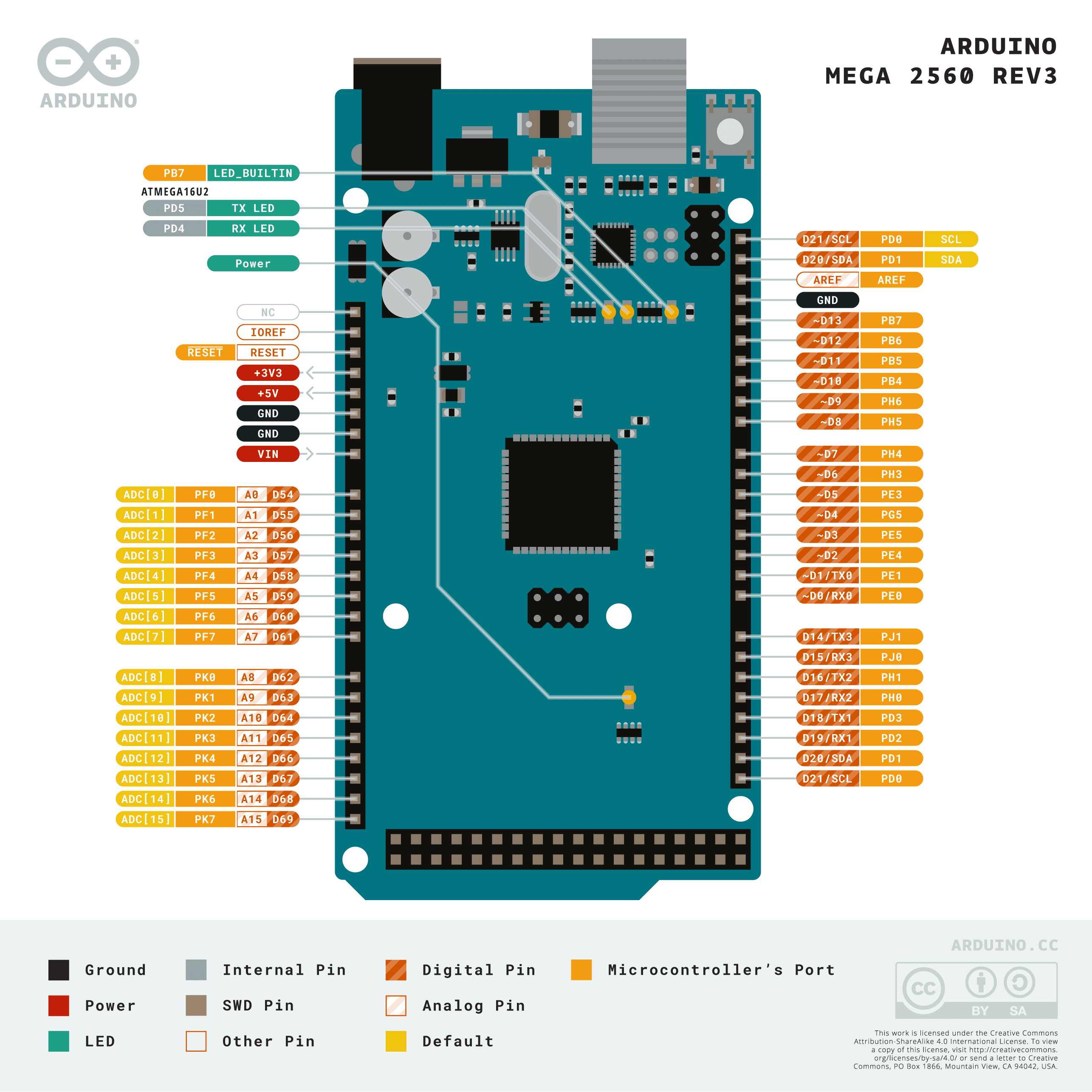
Pinout diagram
| Attr | Specs | verified |
|---|---|---|
mcu | Microchip (ex-Atmel) ATmega2560, 8-bit AVR core, 16 MHz crystal oscillator (board page). The chip belongs to the ATmega640/1280/1281/2560/2561 family described in the Atmel-2549 combined datasheet (the official link used by the store page). | ✔ |
gpu_storage_radios | none — bare-metal MCU board, no WiFi/BT/Ethernet, no filesystem; network or graphics require external modules/shields. | ? unverified |
memory | 256 KB flash (8 KB used by the bootloader → 253,952 bytes of sketch space per boards.txt), 8 KB SRAM, 4 KB EEPROM (store page, "Memory"; EEPROM also highlighted on the board page). | ✔ |
digital_i_o | 54 pins at 5 V logic; each pin 20 mA recommended, 40 mA absolute maximum (exceeding it risks permanent damage), internal pull-ups 20–50 kΩ (store page, "Input and Output"). | ✔ |
pwm | 15 channels (8-bit via analogWrite): pins 2–13 and 44–46 (store page). | ✔ |
analog | 16 inputs, 10-bit resolution (0–1023), reference 5 V by default, adjustable via AREF + analogReference (store page, board page). | ✔ |
serial | 4 hardware UARTs — Serial (0 RX / 1 TX, shared with USB), Serial1 (19/18), Serial2 (17/16), Serial3 (15/14); SoftwareSerial adds more on any digital pin (store page, "Communication"). | ✔ |
other_buses | SPI on 50 (MISO) / 51 (MOSI) / 52 (SCK) / 53 (SS), also on the ICSP header; TWI (I²C) on 20 (SDA) / 21 (SCL); external interrupts on 2 (INT0), 3 (INT1), 21 (INT2), 20 (INT3), 19 (INT4), 18 (INT5) (store page, "Input and Output"). | ✔ |
debug_interface | the ATmega2560 silicon exposes a JTAG interface, disabled by default and enabled via fuse bits (ISP) (ArduinoCore-avr issue #191). | ✔ |
usb | USB-B connector; serial-over-USB handled by an ATmega16U2 (ATmega8U2 on Rev1/Rev2) running USB-to-serial firmware, with its own DFU bootloader (store page, "Programming"). Official USB VID/PID pairs include 0x2341:0x0010 and 0x2A03:0x0010 (boards.txt). | ✔ |
power | USB or 2.1 mm center-positive barrel jack / VIN, auto-selected. Input 6–20 V, recommended 7–12 V; below 7 V the 5 V rail sags, above 12 V the linear regulator can overheat and damage the board. 3V3 pin limited to 50 mA. A resettable 500 mA polyfuse protects the host USB port (store page, "Power" / "Warnings"). | ✔ |
size_weight | PCB max 4 × 2.1 inches (USB and power jack extend beyond), three mounting holes; note the 160 mil gap between digital pins 7 and 8 (not 100 mil). Shipping weight 60 g (store page, "Physical Characteristics", store product JSON). | ✔ |
- Manufacturer: Arduino (arduino.cc / Arduino AG). The board page and store listing are both official Arduino properties (docs.arduino.cc/hardware/mega-2560, store page). Arduino AG has been owned by Qualcomm since October 2025 (Wikipedia — Arduino).
- Year:
- Status: Active — still sold on the official store at €52.80 (SKU A000067, product JSON fetched live; the rendered page's price block does not expose the price to scrapers) (store product JSON), and Microchip lists the ATmega2560 MCU as "Status: In Production" (Microchip product page).
- Launch price:
- Variants: - Rev1 / Rev2 — same ATmega2560, but with an ATmega8U2 USB-serial chip instead of the 16U2; Rev2 added a resistor pulling the 8U2 HWB line to ground to ease DFU mode (store page, "Revisions"). - Rev3 (A000067) — current revision: ATmega16U2, stronger reset circuit, 1.0-pinout SDA/SCL near AREF plus IOREF near RESET (store page, "Revisions"). - Predecessor: the original Arduino Mega (ATmega1280), which the Mega 2560 "replaces" per the official product description (store product JSON). - Mega ADK — accessory-variant of the same platform (ArduinoCore-avr boards.txt). - Sold as "Genuino Mega 2560" outside the US during the 2015–2016 trademark split; the Genuino brand was later dropped (Wikipedia — Arduino). - A huge market of third-party clones (often with a CH340 USB chip instead of the 16U2) — see Problems (forum topic 1192337). - Arduino positions the GIGA R1 WiFi as the modern successor in the same form factor (store product JSON).
+ Strengths
- The I/O king of the AVR family: 54 digital + 16 analog pins, 15 PWM channels and 4 hardware UARTs — the standard way to talk to a GPS + a GSM modem + an RS-485 bus + the PC at the same time (board page, store page).
- Largest AVR memory: 256 KB flash / 8 KB SRAM / 4 KB EEPROM — 8× the flash and 4× the SRAM of the Uno's ATmega328P, and 4× its EEPROM (store page, "Memory" vs Uno board page).
- Uno shield compatibility: digital 0–13, analog 0–5, power header and ICSP sit in Uno-equivalent positions, so most Uno shields drop on (with the I²C caveat below) (store page, "Physical Characteristics and Shield Compatibility").
- R3 header additions: SDA/SCL next to AREF, IOREF near RESET (lets shields detect 5 V vs 3.3 V logic), stronger reset circuit (store page, "Revisions").
- User-serviceable USB layer: the 16U2 is a re-flashable AVR, not a fixed bridge chip — custom USB firmware (HID, MIDI, DFU tricks) is possible on the stock board (store page, "Programming").
- Auto-reset control: DTR-driven reset via a 100 nF capacitor; a labeled RESET-EN trace can be cut to disable it (or bridged back / 110 Ω resistor to 5 V) (store page, "Automatic (Software) Reset").
- On-board polyfuse protecting the host USB port from shorts (>500 mA trips it, self-resets) (store page, "Warnings").
- JTAG debug capability in the silicon (enable via fuses; not wired to a board connector) (ArduinoCore-avr issue #191).
− Weaknesses
- Stock bootloader rejects avrdude erase: with stk500boot_v2_mega2560.hex, avrdude -c stk500v2 fails on the chip-erase step (stk500v2_command: command failed); the older Mega2560-prod-firmware-2011-06-29.hex works — open issue since 2013 (ArduinoCore-avr issue #191).
- USB serial blocks if the host writes without reading: flooding the virtual COM port while nothing reads it can make the board stop responding over USB (16U2 CDC flow-control quirk) (ArduinoCore-avr issue #182).
- DTR auto-reset eats the first bytes: opening the serial port resets the board; the running bootloader "will intercept the first few bytes of data sent to the board after a connection is opened" — host software must wait ~1 s after connecting (store page, "Automatic (Software) Reset").
- USBasp programming pain: "Program doesn't run after Upload Using Programmer with USBasp (Mega2560)" — long-running open issue about fuse/lock handling with cheap USBasp programmers (ArduinoCore-avr issue #246).
- Thermal headroom on the LDO: input range is 6–20 V but only 7–12 V is recommended — "if using more than 12 V, the voltage regulator may overheat and damage the board"; under 7 V the 5 V rail becomes unstable (store page, "Power").
- 3V3 rail is weak: 50 mA maximum — 3.3 V WiFi/GPS modules routinely exceed it and brown out the board (store page, "Power").
- Back-powering hazard: "supplying voltage via the 5V or 3.3V pins bypasses the regulator, and can damage your board" (store page, "Power").
- I²C pin trap: TWI is on 20/21, not on A4/A5 like the old Duemilanove/Diecimila shields expect; Uno shields wired for the pre-R3 I²C location will not talk on a Mega (store page, "Input and Output" / "Shield Compatibility").
- Pin 7/8 spacing: the 160 mil gap between digital pins 7 and 8 breaks pin-continuous stacking of some shields (store page, "Physical Characteristics").
- Clone minefield: CH340-based clones have no 16U2 at all (no DFU recovery path, extra drivers), and some enumerate as an "atmega16u2 DFU" device with no usable COM port; upload failures through the 16U2 on cloned Rev3 designs are a recurring forum topic (topic 1192337, topic 680620, topic 1282040, topic 1300507).
- Damaged-16U2 recovery: a bricked 16U2 makes the USB port invisible until reflashed via DFU or bypassed with an external FTDI cable on pins 0/1 (topic 334623).
- EEPROM endurance:
- Retour d'expérience expert expert — expert-arduino
- Petit retour après quelques mois sur la Mega 2560 Rev3. C'est toujours le roi de l'I/O pour les projets lourds : les 4 UART materiels changent la vie quand on doit gerer un GPS, un modem et le debug PC en parallele sans se casser la tete avec SoftwareSerial. La mmoire de 256Ko est confortable compa… — expert-arduino
- Salut, je bute sur un truc chiant avec ma Mega. J'ai un vieux shield I2C qui marchait niquel sur mon ancien Duemilanove, mais la il ne se passe rien sur la Mega. Je vois bien les cables connectes sur A4/A5 mais le scanner I2C ne trouve aucun priphrique. C'est normal ? Je commence a penser que mon s… — maker-debutant-99
- Pas de panique, ton shield va probablement très bien. Le trou est exactement celui que tu cherches : sur la Mega (et les cartes R3 en general), le bus I2C (TWI) est cbl sur les pins 20 (SDA) et 21 (SCL), pas sur A4/A5 comme sur les vieux Duemilanove ou les premières versions. Il faut juste que tu r… — gigolo-electronique
Community feedback and projects
- Acceleration Due to Gravity: Measuring with Arduino Mega 2560 forum.arduino.cc
- Arduino MEGA 2560 LCD Keypad Shield KMR 1.8 SPI Firmware forum.arduino.cc
- Problem when uploading code arduino mega 2560 forum.arduino.cc
- Problems with Mega 2560 and IDE forum.arduino.cc
- Micro SD on Mega - won't work, odd voltages forum.arduino.cc
- Official board page (specs, EEPROM, 4 UARTs)
- Store page (programming, power, shield compat, revisions)
- Store product JSON (price/SKU/weight, official datasheet link)
- Board datasheet A000067 (PDF)
- ATmega640/1280/1281/2560/2561 combined datasheet (Atmel-2549, linked from the store page)
- Microchip ATmega2560 product page ("In Production")
- Arduino core for AVR — boards.txt (bootloader, fuses, VID/PID)
- 16U2/8U2 firmware sources
- ATmega2560 pin mapping (linked from the store page)
- Getting started guide (linked from the store page)
- Reference
- Reference
- #182
- #191
- #246
- Stock bootloader rejects avrdude erase: with stk500boot_v2_mega2560.hex, avrdude -c stk500v2 fails on the chip-erase step (stk500v2_command: command failed); the older Mega2560-prod-firmware-2011-06-29.hex works — open issue since 2013 (ArduinoCore-avr issue #191).
- USB serial blocks if the host writes without reading: flooding the virtual COM port while nothing reads it can make the board stop responding over USB (16U2 CDC flow-control quirk) (ArduinoCore-avr issue #182).
- DTR auto-reset eats the first bytes: opening the serial port resets the board; the running bootloader "will intercept the first few bytes of data sent to the board after a connection is opened" — host software must wait ~1 s after connecting (store page, "Automatic (Software) Reset").
- USBasp programming pain: "Program doesn't run after Upload Using Programmer with USBasp (Mega2560)" — long-running open issue about fuse/lock handling with cheap USBasp programmers (ArduinoCore-avr issue #246).
- Thermal headroom on the LDO: input range is 6–20 V but only 7–12 V is recommended — "if using more than 12 V, the voltage regulator may overheat and damage the board"; under 7 V the 5 V rail becomes unstable (store page, "Power").
- 3V3 rail is weak: 50 mA maximum — 3.3 V WiFi/GPS modules routinely exceed it and brown out the board (store page, "Power").
- Back-powering hazard: "supplying voltage via the 5V or 3.3V pins bypasses the regulator, and can damage your board" (store page, "Power").
- I²C pin trap: TWI is on 20/21, not on A4/A5 like the old Duemilanove/Diecimila shields expect; Uno shields wired for the pre-R3 I²C location will not talk on a Mega (store page, "Input and Output" / "Shield Compatibility").
- Pin 7/8 spacing: the 160 mil gap between digital pins 7 and 8 breaks pin-continuous stacking of some shields (store page, "Physical Characteristics").
- Clone minefield: CH340-based clones have no 16U2 at all (no DFU recovery path, extra drivers), and some enumerate as an "atmega16u2 DFU" device with no usable COM port; upload failures through the 16U2 on cloned Rev3 designs are a recurring forum topic (topic 1192337, topic 680620, topic 1282040, topic 1300507).
- Damaged-16U2 recovery: a bricked 16U2 makes the USB port invisible until reflashed via DFU or bypassed with an external FTDI cable on pins 0/1 (topic 334623).
- EEPROM endurance:
- Faire clignoter une LED avec l’Arduino Mega 2560 debutant Schéma : IMG-mega-2560-debutant-1-clignotement-led.svg — Arduino Mega 2560, LED avec résistance 330 Ω sur la broche 13, cathode vers la masse
- Lire un bouton poussoir avec résistance de pull-up interne debutant Schéma : IMG-mega-2560-debutant-2-bouton-pull-up.svg — bouton poussoir entre la broche 2 et la masse, résistance de pull-up interne activée, LED témoin sur la broche 13
- Lire un capteur analogique avec l’ADC 10 bits debutant Schéma : IMG-mega-2560-debutant-3-capteur-analogique.svg — potentiomètre 10 kΩ monté en pont diviseur entre 5 V et la masse, curseur vers l’entrée analogique A0 de l’Arduino Mega 2560
- Piloter 15 LED en PWM simultané intermediaire Schéma : IMG-mega-2560-intermediaire-1-pwm-multi-led.svg — barre de 15 LED avec résistances sur les broches PWM 2 à 13 et 44 à 46 de l’Arduino Mega 2560, effet balayage lumineux
- Passerelle série sur les 4 UART matériels intermediaire Schéma : IMG-mega-2560-intermediaire-2-passerelle-4-uart.svg — Arduino Mega 2560 reliant le PC (USB/Serial), un module GPS sur Serial1 (19/18), un module sur Serial2 (17/16) et un bus RS-485 sur Serial3 (15/14)
- Afficher sur un LCD 16×2 en bus parallèle 8 bits intermediaire Schéma : IMG-mega-2560-intermediaire-3-lcd-16x2.svg — écran LCD 16×2 à contrôleur HD44780 câblé en bus 8 bits sur les broches 22 à 32 de l’Arduino Mega 2560, potentiomètre de contraste sur V0
- Programmer en registres AVR : timer 16 bits et interruption avance Schéma : IMG-mega-2560-avance-1-registres-timer16.svg — schéma fonctionnel du timer 16 bits TCNT1 de l’ATmega2560 en mode CTC avec OCR1A, prédiviseur 1024 et bascule de la broche PB7 pilotée par l’interruption TIMER1_COMPA
- Enregistrer des données sur carte SD via le bus SPI avance Schéma : IMG-mega-2560-avance-2-spi-sd-card.svg — module carte SD 3,3 V connecté au bus SPI de l’Arduino Mega 2560 (MISO 50, MOSI 51, SCK 52, SS 53) avec adaptation de niveaux 5 V vers 3,3 V
- Mode power-down, watchdog et journalisation EEPROM avance Schéma : IMG-mega-2560-avance-3-low-power-watchdog-eeprom.svg — cycle de veille de l’ATmega2560 : mesure, écriture dans l’EEPROM 4 Ko en mémoire tampon circulaire, mise en sommeil power-down, réveil par le watchdog
Code library — examples written for this board
clignotante.inoArduinobouton-led.inoArduinodouble-servo.inoArduinopont-uart.inoArduinopwm-respiration.inoArduinopotentiometre-plotter.inoArduinoscan-16-analogiques.inoArduinoscanner-i2c.inoArduinobarrieron-8led.inoArduinobuzzer-melodie.inoArduino
Examples and repos found online
- arduino/ArduinoCore-avr github.com
- arduino-libraries/Servo github.com
- arduino-libraries/Ethernet github.com
- arduino-libraries/SD github.com
- GreyGnome/EnableInterrupt github.com