M5Stack Core (ESP32) — Basic / Gray family (K001 / K002)
⚡ The essentials in 60 seconds
- soc — Espressif ESP32-D0WDQ6-V3, dual-core 32-bit Xtensa LX6 @ up to 240 MHz, 600 DMIPS, 520 KB SRAM (shop v2.7 page: "ESP32-D0WDQ6-V3@Dual-core processor, 240MHz"; basic.md: "240MHz dual core, 600 DMIPS, 520KB SRAM"). >
- gpu — none (LCD driven over SPI by a display controller).
- memory — 16 MB SPI flash (units before 2020.6 shipped 4 MB — official change log "2020.6 Flash size changed from 4MB to 16MB", basic.md). No PSRAM on Basic/Gray (Core2 adds 8 MB PSRAM —
- storage — microSD/TF slot, SPI (CS=GPIO4), max 16 GB (basic.md PinMap + "TF card slot (16G Maximum size)").
- display — 2.0-inch 320×240 TFT LCD, driver ILI9342C, IPS, max brightness 853 nit (shop v2.7 page: "2.0\"@320 x 240 ILI9342C IPS panel"; basic.md same). Pre-2019.7 units shipped a TN panel ("2019.7 TN screen changed to IPS screen", basic.md). >
- audio — built-in 1 W-0928 speaker driven directly from ESP32 DAC1 (GPIO25) — it is a DAC-driven speaker, not a passive buzzer (basic.md PinMap "Speaker / DA PIN / GPIO25"; M5Stack library header "SPEAKER on DAC pin 25" I2S lines (BCK=GPIO12, WS=GPIO13, DOUT=GPIO15, DIN=GPIO34) are routed to the M-BUS for external audio (M5Unified GPIO table, op. cit.). No onboard microphone on Basic/Gray (GO/FIRE add a mic on GPIO34 — M5Unified table "MIC_ADC GPIO34").
- On this board : 9 tutorials · 10 code
The M5Stack Core, specifically the Basic and Gray variants often identified by SKUs K001 and K002, represents the foundational entry point into the world of modular Internet of Things development. Released in July 2017, this device is not merely a bare circuit board but a fully enclosed, stackable computer kit designed to lower the barrier to entry for hobbyists and engineers alike. At its heart lies the Espressif ESP32-D0WDQ6-V3, a dual-core 32-bit microcontroller based on the Xtensa LX6 architecture. For those unfamiliar with these terms, a dual-core processor means the chip has two independent processing units, allowing it to handle multiple tasks simultaneously, such as maintaining a Wi-Fi connection while updating the display. Running at speeds up to 240 MHz, this processor provides substantial computing power for embedded applications, supported by 520 KB of SRAM for immediate data access. The current revision, Basic v2.7, comes equipped with 16 MB of SPI flash storage, a significant increase from the 4 MB found in units manufactured before June 2020. It is important to note that unlike its successor, the Core2, the original Core does not include PSRAM, which limits its ability to handle very large datasets or complex graphical interfaces in memory.
The user interface of the M5Stack Core is self-contained, featuring a 2.0-inch TFT LCD display with a resolution of 320 by 240 pixels. This screen is driven by an ILI9342C controller over an SPI interface, which is a standard communication protocol for connecting peripherals to microcontrollers. A notable historical detail for users with older hardware is the transition from TN to IPS panel technology in July 2019. IPS panels offer wider viewing angles and better color reproduction, but this change required software updates to prevent color inversion issues on newer libraries. The device also includes three programmable front buttons labeled A, B, and C, connected to GPIO pins 39, 38, and 37 respectively. These pins are input-only, meaning they are ideal for reading button presses but cannot be used to control external outputs. For audio feedback, the Core features a 1-watt speaker driven directly by the ESP32’s internal Digital-to-Analog Converter on GPIO25. This allows for tone generation and simple audio playback without the need for an external audio amplifier chip, although it does mean that the speaker shares this pin with one of the analog-to-digital converter channels, creating a hardware conflict if both are used simultaneously.
Power management is handled by the IP5306 power management IC, which manages charging, voltage boosting, and soft power latching. This component allows the device to be powered by a standard USB-C connection while simultaneously charging the internal lithium-polymer battery. The battery capacity is 110 mAh at 3.7 volts, a specification that was reduced from 150 mAh in March 2020. The IP5306 communicates with the main processor via an I2C bus at address 0x75, enabling software to check battery levels and control power states. However, users should be aware that the battery percentage reported is based on coarse voltage thresholds rather than precise fuel gauging, so it should be treated as an approximate indicator. The device turns on with a single click of the red side button and powers off with a double-click, a feature that can sometimes confuse new users if they are not aware of the latching mechanism.
Connectivity is a strong suit of the ESP32 platform, and the M5Stack Core supports Wi-Fi 802.11 b/g/n on the 2.4 GHz band and dual-mode Bluetooth, including both classic Bluetooth and Bluetooth Low Energy. This makes it suitable for a wide range of wireless applications, from home automation to data logging. For expansion, the device utilizes a unique modular system. The bottom edge features the M-BUS connector, a set of pogo pins that allows the Core to stack physically and electrically with various "Base" modules. Additionally, three Grove ports are available on the side, providing easy access to I2C, DAC/ADC, and UART interfaces for connecting sensors and actuators using standard Grove cables. This modularity is central to the M5Stack philosophy, allowing users to build complex systems by snapping together pre-wired components without soldering.
Software support for the M5Stack Core is extensive, catering to different skill levels and preferences. The most common development environment is the Arduino IDE, where users can install the ESP32 board package and use the M5Unified and M5GFX libraries to control the hardware. These libraries abstract the low-level details of the display, buttons, and power management, allowing developers to write high-level code quickly. For those who prefer visual programming or rapid prototyping, M5Stack offers UIFlow, a firmware that supports both Blockly and MicroPython. UIFlow can be flashed using the M5Burner tool and allows for programming via a web-based IDE or a desktop application. While standard MicroPython can run on the device, it lacks built-in drivers for the specific M5Stack hardware, so users are generally directed to UIFlow for a smoother experience. It is worth noting that the classic M5Stack library is now deprecated in favor of M5Unified, so new projects should start with the newer libraries to ensure compatibility and support.
There are several important distinctions and potential pitfalls to consider when working with this hardware. The M5Stack Core family includes several variants. The Basic version lacks an Inertial Measurement Unit, while the Gray version includes one. The IMU in the Gray model has undergone several changes over its production life, moving from MPU6050 to MPU9250 and finally to MPU6886 with a BMM150 magnetometer. Code written for one IMU may not work on another without auto-detection logic. Furthermore, the Core should not be confused with the Core2 or CoreS3, which are distinct successors with different hardware features such as capacitive touch screens, microphones, and more powerful processors. The original Core has no touch capability, no microphone, and no real-time clock. Another critical consideration is the operating temperature range, which is specified as 0°C to 40°C. Despite its robust plastic casing, the device is not designed for extreme environmental conditions, and exposure to higher temperatures can lead to failure. Finally, the TF card slot supports a maximum capacity of 16 GB, a limitation that stems from the file system and driver implementation, so larger cards will not function correctly.
The M5Stack Core remains a relevant and powerful tool for learning and prototyping. Its combination of a capable ESP32 processor, integrated display and audio, and modular expansion capabilities makes it an ideal platform for projects ranging from simple data loggers to complex IoT gateways. The active community and extensive library support ensure that developers have access to a wealth of resources and examples. Whether you are a beginner looking to understand the basics of embedded systems or an experienced engineer needing a quick prototyping platform, the M5Stack Core offers a balanced and accessible entry point into the world of connected devices. By understanding its hardware constraints, such as the ADC conflicts and power management specifics, users can avoid common pitfalls and make the most of this versatile development kit.
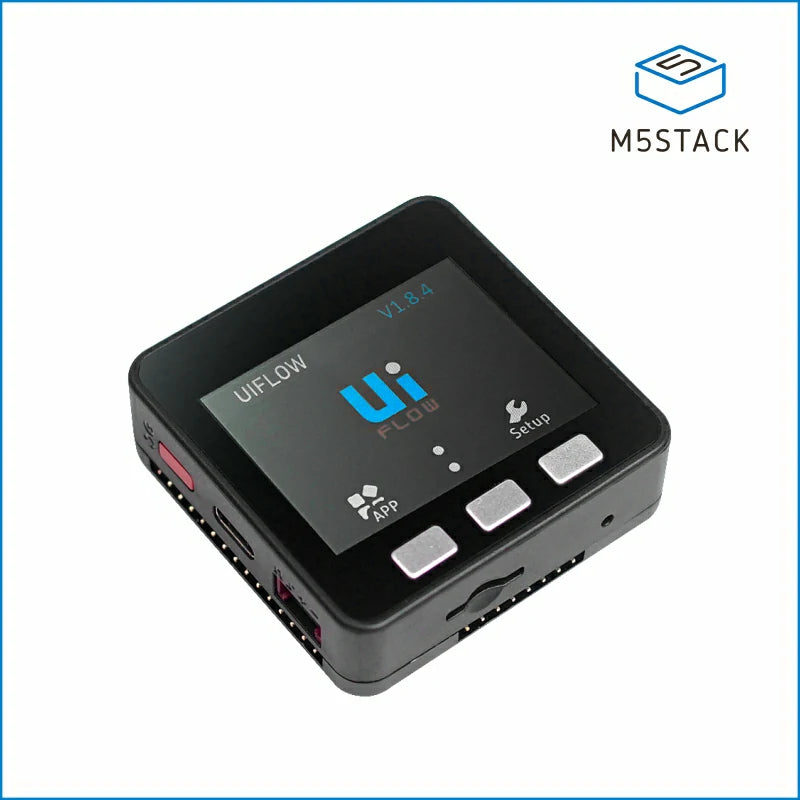
Pinout diagram
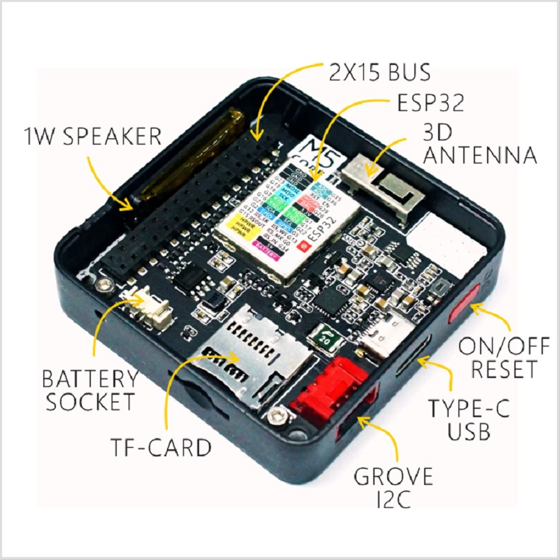
| Attr | Specs | verified |
|---|---|---|
soc | Espressif ESP32-D0WDQ6-V3, dual-core 32-bit Xtensa LX6 @ up to 240 MHz, 600 DMIPS, 520 KB SRAM (shop v2.7 page: "ESP32-D0WDQ6-V3@Dual-core processor, 240MHz"; basic.md: "240MHz dual core, 600 DMIPS, 520KB SRAM"). > | ? unverified |
gpu | none (LCD driven over SPI by a display controller). | ? unverified |
memory | 16 MB SPI flash (units before 2020.6 shipped 4 MB — official change log "2020.6 Flash size changed from 4MB to 16MB", basic.md). No PSRAM on Basic/Gray (Core2 adds 8 MB PSRAM — | ✔ |
storage | microSD/TF slot, SPI (CS=GPIO4), max 16 GB (basic.md PinMap + "TF card slot (16G Maximum size)"). | ? unverified |
display | 2.0-inch 320×240 TFT LCD, driver ILI9342C, IPS, max brightness 853 nit (shop v2.7 page: "2.0\"@320 x 240 ILI9342C IPS panel"; basic.md same). Pre-2019.7 units shipped a TN panel ("2019.7 TN screen changed to IPS screen", basic.md). > | ? unverified |
audio | built-in 1 W-0928 speaker driven directly from ESP32 DAC1 (GPIO25) — it is a DAC-driven speaker, not a passive buzzer (basic.md PinMap "Speaker / DA PIN / GPIO25"; M5Stack library header "SPEAKER on DAC pin 25" I2S lines (BCK=GPIO12, WS=GPIO13, DOUT=GPIO15, DIN=GPIO34) are routed to the M-BUS for external audio (M5Unified GPIO table, op. cit.). No onboard microphone on Basic/Gray (GO/FIRE add a mic on GPIO34 — M5Unified table "MIC_ADC GPIO34"). | ✔ |
buttons | 3 programmable front buttons A=GPIO39, B=GPIO38, C=GPIO37; red side power button (click = power on, double-click = power off via IP5306) (basic.md). | ? unverified |
battery_power | 110 mAh @ 3.7 V LiPo (150 mAh before 2020.3), IP5306 power-management IC (custom I2C edition, address 0x75 on G21/G22) handling charge, boost and soft power latching; power input 5 V @ 500 mA over USB-C; measured charging current 0.55 A (basic.md; gray.md). | ? unverified |
usb | USB Type-C for power/programming; CH9102F USB-serial bridge on v2.7 (shop v2.7 page), CP2104 on earlier revisions (UIFlow/Arduino quick-starts reference the CP210X driver). | ? unverified |
wireless | Wi-Fi 802.11 b/g/n 2.4 GHz + dual-mode Bluetooth (classic + BLE, per ESP32; basic.md "Wi-Fi, dual mode Bluetooth"; ESP32 datasheet 2.4 G 3D antenna (shop page). | ✔ |
expansion_buses | - M-BUS bottom edge connector (the "pogo"/stacking pins) — Basic v2.7 exposes 15 IO leads: G21, G22, G23, G19, G18, G3, G1, G16, G17, G2, G5, G25, G26, G35, G36 (shop v2.7 page; older docs list 14: G1,2,3,16,17,18,19,21,22,23,25,26,35,36 — basic.md). > | ? unverified |
gpio_electrical_analog_esp32_classic | 3.3 V logic; ADC1 8 ch (G32–39), ADC2 10 ch (G0/2/4/12–15/25–27), DAC1=G25 (speaker), DAC2=G26 (basic.md "ESP32 ADC/DAC" table; ESP32 datasheet). | ? unverified |
mechanical | 54 × 54 × 17 mm (v2.7; 18/18.9 mm on older docs), ~47–53 g; case material: Plastic (PC) — not aluminium (shop v2.7 page; basic.md/gray.md). Magnets on the back for DIN-rail/panel mounting ("Magnetic suction at back", basic.md). | ? unverified |
operating_temperature | 0 °C to 40 °C (32–104 °F) (basic.md/gray.md). | ? unverified |
power_consumption | ? unverified |
- Manufacturer: M5Stack (Shenzhen M5Stack Technology Co., Ltd.) — product line "M5Core", SKU K001 (Basic), K002 (Gray) ( — archived source of docs.m5stack.com).
- Released: July 2017 — official version-change table: "2017.7 Initial public release" (basic.md, op. cit.). Widely reported as launched via a Kickstarter campaign in Aug 2017. >
- Status: Active (current revision Basic v2.7) — sold in stock on the official shop at US$39.90 as of 2026-10-13 ("ESP32 Basic Core IoT Development Kit V2.7", Older revisions Basic v1.0, v2.6 and Gray v1.0 are marked EOL by M5Stack (
- Variants (same Core generation): - Basic (K001) — no IMU; revisions v1.0 → v2.6 → v2.7 (basic.md; shop page). - Gray (K002) — Basic + IMU (see Problems for the sensor swaps) (gray.md). - GO / FIRE — Basic/Gray derivatives with mic (GO) and ESP-NET/LoRa options (FIRE); listed as supported devices "M5Stack (Basic / Gray / GO / Fire)" ( - FACES — variant with keyboard base (UIFlow quick-start applies to "BASIC / GRAY / M5GO / FIRE / FACES kit") (
- Successors (different cards): Core2 (K010, 2020), CoreInk, CoreS3 (ESP32-S3), Tough.
+ Strengths
- Stackable modular system: M-BUS bottom connector + magnetic base lets the Core stack with 30+ "Base" modules and 40+ "Unit" (Grove) sensors, plug-and-play (basic.md description: "Together with 30+ M5Stack stackable modules, 40+ extendable units…").
- Software-controlled power: IP5306 PMIC gives soft power on/off (double-click red button), charge control and battery-level readback over I2C 0x75 (basic.md; gray.md; M5Stack library M5.Power API).
- Three programmable buttons + DAC speaker + 2.0" color LCD + TF card in a 54 mm cased kit — a self-contained HMI terminal without external parts (basic.md).
- Huge software ecosystem: official Arduino/M5Unified/M5GFX/UIFlow stacks plus community frameworks (M5ez, cfGUI, GUIslice, SD-Updater menu system…) catalogued in the M5Stack library README "USER CASES" (
- LVGL graphics: the UIFlow firmware integrates an LVGL-based UI component library (m5stack_ui: M5Screen/M5Label/M5Btn/M5Bar/M5Slider/…), and M5GFX (a LovyanGFX derivative per its license section) is the modern display driver for Arduino/ESP-IDF (
- Core vs Core2 (do not confuse): Core2 (K010) adds a capacitive touch screen (FT6336U) with 3 virtual on-screen buttons, 8 MB PSRAM, I2S audio (NS4168 amp + PDM mic SPM1423), RTC BM8563, AXP192 PMU, vibration motor, 390 mAh battery, CP2104; ES8311 appears in other M5 products (e.g.
- IMU is a Gray (or later) feature, not Basic: Basic has no IMU; Gray's sensor history is MPU6050+MAG3110 (2017.9) → MPU9250 (2017.12) → MPU6886 + BMM150 (2019.6) (gray.md version table). >
− Weaknesses
- TN→IPS screen swap inverted colors (2019.7): official note — "upgrade your M5Stack lib to the latest version (after 0.2.8) to solve screen reverse color problem" (basic.md version table). Mixed fleets of pre/post-2019.7 units need a library version that auto-detects.
- Silent IMU part swaps: Gray went MPU6050+MAG3110 → MPU9250 → MPU6886+BMM150; Basic/Gray units use MPU6886 or SH200Q depending on production ("accelerometer type depends on version of Basic/Gray" — gray.md; IMU code must probe/auto-select.
- Flash size change 4 MB → 16 MB (2020.6) (basic.md): partition tables and examples sized for 4 MB mis-report capacity; OTA/partition choices differ by unit age.
- USB-serial chip change CP2104 → CH9102F (v2.7): older quick-starts tell you to install the CP210X driver (Arduino/UIFlow quick-starts), but v2.7's spec table lists CH9102F (shop page) — wrong driver = "no COM port" on new units.
- Battery spec change 150 → 110 mAh (2020.3) (basic.md) and coarse voltage-threshold gauge: IP5306 battery % is a 5-step voltage band table (e.g. 3.81–3.55 V → "50%") — don't expect fuel-gauge accuracy (basic.md "IP5306 charging/discharging, Voltage parameter").
- Power latching surprises: the unit only turns on with the red button and off with a double-click; software M5.Power.powerOFF cuts the boost — a sketch that powers off can look "bricked" until the button is pressed again (basic.md power on/off; M5Stack.h Power API).
- Speaker shares DAC1 (GPIO25), which is also ADC2_CH0 (basic.md ADC/DAC + PinMap tables): you cannot use the speaker and that ADC channel together; and ADC2 as a whole is unusable while Wi-Fi runs on ESP32 (Espressif ADC doc
- Buttons A/B/C sit on input-only pins GPIO39/38/37 (basic.md) — fine for buttons, but those pins can't drive outputs and have no internal pull-downs (ESP32 datasheet).
- Basic has no IMU/mic/RTC/PSRAM/touch — code copied from Gray/Core2 examples fails silently (basic.md vs gray.md vs core2.md feature tables).
- Legacy library deprecated: the classic M5Stack Arduino library is marked "🚫 Deprecated — Use M5GFX & M5Unified" ( new projects should use M5Unified/M5GFX.
- TF card ceiling 16 GB (basic.md) — larger cards fail; classic FAT32/≤16 GB requirement.
- ESP32-classic platform issues apply (ADC nonlinearity, ADC2/Wi-Fi conflict, brownout resets on weak 5 V supplies, strapping-pin traps): official errata
- Core2-specific traps (context): AXP192 requires passing the right mbus_mode to M5.begin, and stacking Core2 onto M5 bases requires removing its battery bottom (core2.md notes).
- Operating range only 0–40 °C despite "industrial grade case" marketing (basic.md) — not for hot enclosures.
- Retour d'expérience expert expert — expert-microcontroleur
- Retour sur la M5Stack Core Basic v2.7. C'est un kit solide avec son écran IPS 2.0 pouces et son boîtier empilable via le M-BUS, idéal pour prototyper vite grâce à l'écosystème M5Unified. Attention aux pièges de la v2.7 : le pont USB est désormais un CH9102F, pas le CP2104 des anciennes versions, do… — expert-microcontroleur
- Merci pour ce résumé. J'ai justement un souci avec l'alimentation. Je trouve ça bizarre qu'il faille double-cliquer sur le bouton rouge pour éteindre proprement. Parfois je pense que la carte est morte alors qu'elle est juste éteinte, et il faut appuyer à nouveau pour la réveiller. Est-ce que le ni… — maker_debutant_88
- C'est normal. Le circuit IP5306 gère la mise en veille logicielle, donc un powerOFF dans le code coupe le boost sans débrancher physiquement, d'où l'aspect 'brique' temporaire. Pour la batterie, ne t'attend pas à une précision de jauge : la datasheet indique que le pourcentage est calculé par bande… — expert-microcontroleur
Community feedback and projects
- M5Stack - confused about I2C bus voltage arduino.stackexchange.com
- Advantage of 3MP OV3660 sensor on the ESP32 M5Stack camera? arduino.stackexchange.com
- Quadrupted TOY Robot "M5QSpider" hackaday.io
- AI hardware for camera stream processing - Node-RED Forum discourse.nodered.org
- IIC_IP5306_REG_V1.4_cn.pdf datasheet
- TN→IPS screen swap inverted colors (2019.7): official note — "upgrade your M5Stack lib to the latest version (after 0.2.8) to solve screen reverse color problem" (basic.md version table). Mixed fleets of pre/post-2019.7 units need a library version that auto-detects.
- Silent IMU part swaps: Gray went MPU6050+MAG3110 → MPU9250 → MPU6886+BMM150; Basic/Gray units use MPU6886 or SH200Q depending on production ("accelerometer type depends on version of Basic/Gray" — gray.md; IMU code must probe/auto-select.
- Flash size change 4 MB → 16 MB (2020.6) (basic.md): partition tables and examples sized for 4 MB mis-report capacity; OTA/partition choices differ by unit age.
- USB-serial chip change CP2104 → CH9102F (v2.7): older quick-starts tell you to install the CP210X driver (Arduino/UIFlow quick-starts), but v2.7's spec table lists CH9102F (shop page) — wrong driver = "no COM port" on new units.
- Battery spec change 150 → 110 mAh (2020.3) (basic.md) and coarse voltage-threshold gauge: IP5306 battery % is a 5-step voltage band table (e.g. 3.81–3.55 V → "50%") — don't expect fuel-gauge accuracy (basic.md "IP5306 charging/discharging, Voltage parameter").
- Power latching surprises: the unit only turns on with the red button and off with a double-click; software M5.Power.powerOFF cuts the boost — a sketch that powers off can look "bricked" until the button is pressed again (basic.md power on/off; M5Stack.h Power API).
- Speaker shares DAC1 (GPIO25), which is also ADC2_CH0 (basic.md ADC/DAC + PinMap tables): you cannot use the speaker and that ADC channel together; and ADC2 as a whole is unusable while Wi-Fi runs on ESP32 (Espressif ADC doc
- Buttons A/B/C sit on input-only pins GPIO39/38/37 (basic.md) — fine for buttons, but those pins can't drive outputs and have no internal pull-downs (ESP32 datasheet).
- Basic has no IMU/mic/RTC/PSRAM/touch — code copied from Gray/Core2 examples fails silently (basic.md vs gray.md vs core2.md feature tables).
- Legacy library deprecated: the classic M5Stack Arduino library is marked "🚫 Deprecated — Use M5GFX & M5Unified" ( new projects should use M5Unified/M5GFX.
- TF card ceiling 16 GB (basic.md) — larger cards fail; classic FAT32/≤16 GB requirement.
- ESP32-classic platform issues apply (ADC nonlinearity, ADC2/Wi-Fi conflict, brownout resets on weak 5 V supplies, strapping-pin traps): official errata
- Core2-specific traps (context): AXP192 requires passing the right mbus_mode to M5.begin, and stacking Core2 onto M5 bases requires removing its battery bottom (core2.md notes).
- Operating range only 0–40 °C despite "industrial grade case" marketing (basic.md) — not for hot enclosures.
- Bonjour l'écran : premier texte sur le TFT 320×240 debutant Schéma : IMG-m5stack-core-esp32-debutant-1-m5stack-core-esp32-ecran-bonjour.svg — M5Stack Core vu de face, écran allumé affichant Hello M5Stack, câble USB-C branché, flèches vers l'écran ILI9342C 320×240
- Les 3 boutons A, B, C et le haut-parleur interne debutant Schéma : IMG-m5stack-core-esp32-debutant-2-m5stack-core-esp32-boutons-ab-c.svg — M5Stack Core de face avec les trois boutons avant surlignés et leurs broches GPIO39 (A), GPIO38 (B), GPIO37 (C), haut-parleur 1 W sur GPIO25 indiqué à l'arrière
- Console série et capteur analogique sur PORT.B debutant Schéma : IMG-m5stack-core-esp32-debutant-3-m5stack-core-esp32-console-serie-capteur.svg — M5Stack Core avec câble USB vers un PC affichant le moniteur série à 115200 bauds et un capteur analogique branché sur le connecteur Grove PORT.B (G26/G36)
- Graphismes avancés avec M5GFX : formes, couleurs et luminosité intermediaire Schéma : IMG-m5stack-core-esp32-intermediaire-1-m5stack-core-esp32-graphismes-m5gfx.svg — écran de l'M5Stack Core divisé en zones annotées montrant rectangles, cercles, lignes et texte dessinés par M5GFX, curseur de luminosité en bas
- Bus I2C : scanner PORT.A et lecture de la batterie IP5306 intermediaire Schéma : IMG-m5stack-core-esp32-intermediaire-2-m5stack-core-esp32-i2c-grove-batterie.svg — M5Stack Core avec le connecteur Grove PORT.A (rouge, SDA G21 / SCL G22) relié à un petit capteur I2C, adresse 0x75 de la puce IP5306 indiquée à l'intérieur du boîtier
- Wi-Fi 2,4 GHz et horloge NTP sur l'écran intermediaire Schéma : IMG-m5stack-core-esp32-intermediaire-3-m5stack-core-esp32-wifi-ntp.svg — M5Stack Core relié par des ondes Wi-Fi 2,4 GHz à une box Internet puis à un serveur NTP, écran affichant date et heure, mention « pas de RTC : remise à zéro à chaque redémarrage »
- Deep-sleep, réveil minuteur et bouton, autonomie sur batterie avance Schéma : IMG-m5stack-core-esp32-avance-1-m5stack-core-esp32-deep-sleep.svg — M5Stack Core en coupe avec batterie 110 mAh et puce IP5306, chronomètre de réveil deep-sleep, bouton rouge d'alimentation et bouton BOOT GPIO0 en réveil externe, cycle mesure/réveil/sommeil
- Enregistreur de capteurs sur carte microSD (slot interne) avance Schéma : IMG-m5stack-core-esp32-avance-2-m5stack-core-esp32-enregistreur-sd.svg — M5Stack Core de trois quarts avec trappe arrière, carte microSD insérée dans le slot interne (CS GPIO4, max 16 Go FAT32), écran affichant le nombre de lignes enregistrées et fichier CSV sur la carte
- Tableau de bord MQTT temps réel sur l'écran avance Schéma : IMG-m5stack-core-esp32-avance-3-m5stack-core-esp32-mqtt-dashboard.svg — M5Stack Core affichant un tableau de bord (température, batterie, statut) connecté par Wi-Fi à un courtier MQTT, autres capteurs publiant vers le même courtier
Code library — examples written for this board
hello-ecran.inoArduinoboutons.inoArduinomelodie.inoArduinometeo.inoArduinojournal-sd.inoArduinogrove-dht12.inoArduinosonometre.inoArduinobatterie.inoArduinoreveil.inoArduinom5_hello.pyMicroPython
Examples and repos found online
- m5stack/M5Stack github.com
- m5stack/M5Unified github.com
- m5stack/M5GFX github.com