Arduino Esplora — Board Fiche
⚡ The essentials in 60 seconds
- mcu — Atmel/Microchip ATmega32u4 — 8-bit AVR RISC, single core, 16 MHz crystal (build.f_cpu=16000000L), with integrated USB 2.0 full-speed device transceiver (no USB-serial chip) (boards.txt, Microchip, datasheet PDF).
- gpu — none.
- memory — Flash 32 KB (4 KB bootloader → 28,672 B sketch space, upload.maximum_size=28672); SRAM 2.5 KB (2560 B, upload.maximum_data_size=2560); EEPROM 1 KB (EEPROM library).
- usb — micro-USB connector, native CDC virtual COM port; can also enumerate as keyboard/mouse (HID). IDs: VID 0x2341, PID 0x803C (sketch) / 0x003C (bootloader); legacy VID 0x2A03 also matched (boards.txt).
- operating_voltage — 5 V logic (tech specs table, retired page).
- power — the official page describes powering the board by connecting it to a computer with a USB cable; a resettable polyfuse (~500 mA) protects the host USB port (retired page, "USB Overcurrent Protection"). No barrel jack or Vin/GND power header is documented anywhere on the official page.
- On this board : 9 tutorials · 10 code
Imagine a microcontroller board that feels less like a piece of electronic hardware and more like a handheld gaming console. This is the Arduino Esplora, a unique entry in the Arduino family that was designed specifically for beginners, educators, and hobbyists who want to start creating interactive projects without needing to understand the complexities of electronics first. Launched in 2012, the Esplora was a pioneering product because it came with a comprehensive suite of sensors and actuators already built directly onto the board. Unlike standard Arduino boards, where you typically need to buy separate components and wire them together using breadboards and jumper cables, the Esplora allows you to start coding immediately. It features an analog joystick, four push-buttons arranged in a diamond pattern, a linear slider, a microphone, a light sensor, a temperature sensor, and a three-axis accelerometer. On the output side, it includes a buzzer for sound and a bright RGB LED that can display any color. The physical layout deliberately mimics a game controller, with the joystick on the left and buttons on the right, making it intuitive for anyone familiar with video games.
At its core, the Esplora is technically very similar to the Arduino Leonardo. It uses the same Atmel ATmega32u4 microcontroller, which is an 8-bit AVR processor running at a clock speed of 16 MHz. To explain this simply, the "clock speed" refers to how many cycles the processor can perform per second, determining how fast it can execute your code. The ATmega32u4 is particularly special because it has built-in USB communication capabilities. This means the board can connect to a computer via a micro-USB cable and be recognized directly as a USB device, such as a keyboard or a mouse, without needing extra chips. This native USB HID (Human Interface Device) capability is what allows the Esplora to act as a custom game controller for your computer. The board has 32 KB of flash memory for storing your programs, with about 28 KB available for user sketches after accounting for the bootloader, and 2.5 KB of SRAM for temporary data storage. While these numbers seem small compared to modern smartphones, they are more than sufficient for the types of interactive projects the Esplora was designed for.
One of the most important technical aspects of the Esplora to understand is how its many sensors are connected to the microcontroller. Because the ATmega32u4 has a limited number of analog input pins, the Esplora uses a clever trick called an analog multiplexer. Think of this as a switchboard operator that routes signals from many different sensors to a single input pin. Most of the sensors, including the joystick axes, buttons, slider, light sensor, temperature sensor, and microphone, share one analog input pin (A4). The microcontroller selects which sensor to read by changing the voltage levels on four other pins (A0 to A3). This design choice has significant implications for programming. You cannot read two of these multiplexed sensors at the exact same instant; you must read them one after another. Furthermore, because these pins are dedicated to the internal sensors, they are not available for you to connect external components. The only general-purpose digital pins explicitly documented as free for external use are D3 and D11. This limitation is a key reason why the Esplora is not compatible with standard Arduino shields, which rely on a specific arrangement of header pins that the Esplora does not have. Instead, it offers two TinkerKit connectors for easy expansion with color-coded modules and a socket for an optional TFT LCD screen.
The Esplora was programmed using the standard Arduino IDE, and its software ecosystem is built around a dedicated Esplora library. This library simplifies coding by providing high-level commands that handle the complex multiplexer logic for you. Instead of writing code to toggle address pins and wait for signals to settle, you can simply call functions like Esplora.readSlider or Esplora.writeRGB. The library also provides pre-processed values, such as converting the raw sensor data from the temperature sensor into degrees Celsius, although it is worth noting that this conversion uses integer math and is an approximation rather than a highly precise calibrated measurement. Similarly, the accelerometer readings rely on hard-coded zero-offset values, which means that individual boards may have slight variations in their readings, and users might need to recalibrate for their specific unit. The board is powered entirely via the USB connection, protected by a resettable fuse, so it does not have a traditional power jack. This makes it ideal for projects that stay connected to a computer, but it requires external battery solutions for standalone operation.
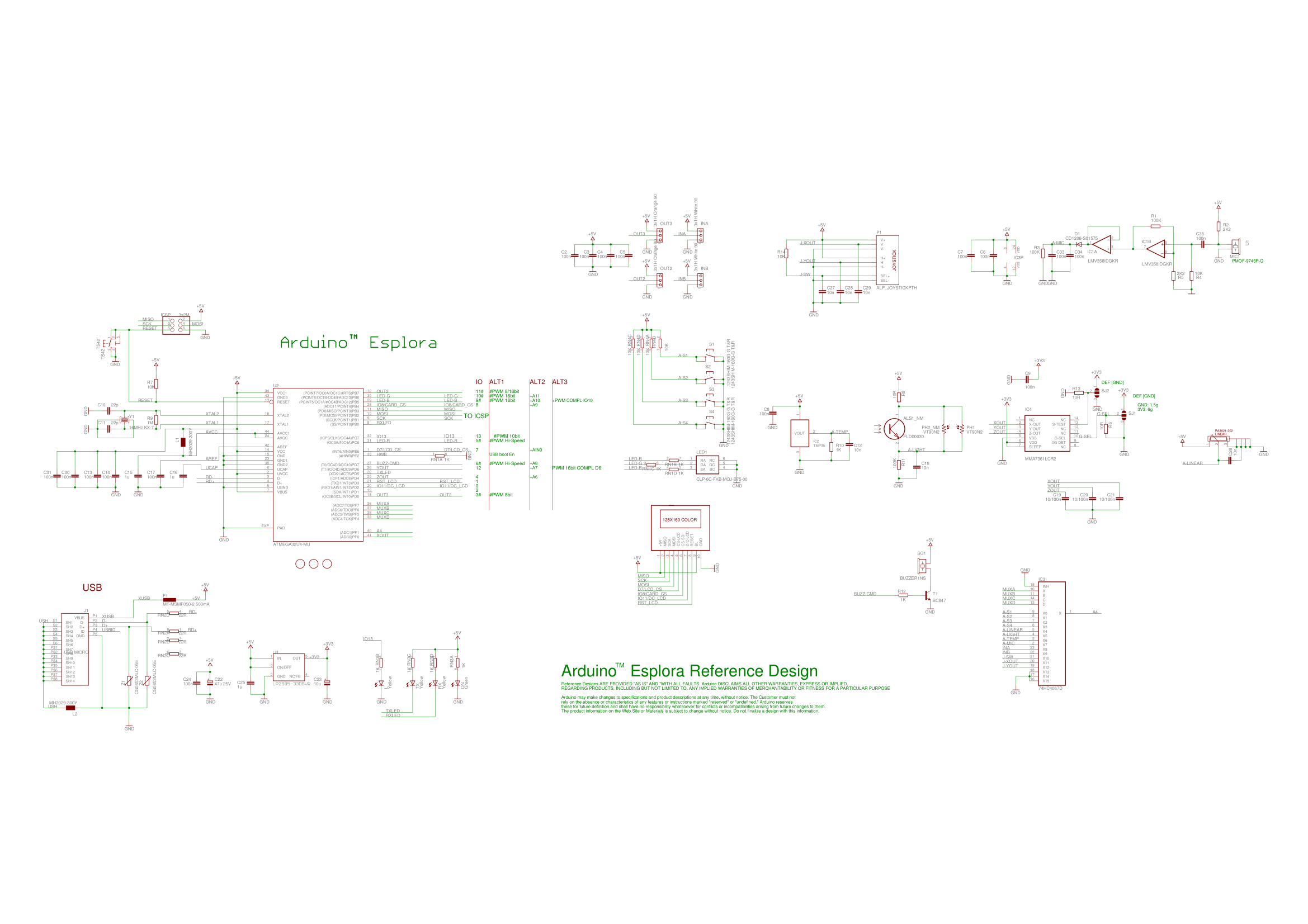
Despite its innovative design, the Arduino Esplora is now considered end-of-life and has been retired from the official Arduino product line. It is no longer sold in the official store, and its documentation has been moved to the archived section of the Arduino website. However, it remains a beloved board in the maker community, particularly for educational settings and for creating custom input devices. The hardware is open-source, with full schematics and reference designs available, allowing enthusiasts to repair or even manufacture their own versions. While newer boards like the Arduino Nano Every or the ESP32-based boards offer more power and flexibility, the Esplora holds a special place in history as the first Arduino to truly embrace the "all-in-one" interactive experience. It lowered the barrier to entry for coding by removing the intimidation factor of wiring circuits, allowing users to focus purely on logic and creativity. Whether you are building a simple music toy using the slider and buzzer, a Pong game on the optional screen, or a complex remote control for your PC, the Esplora’s integrated design makes it a charming and accessible platform for learning the fundamentals of physical computing.

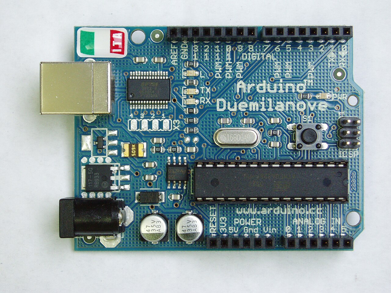
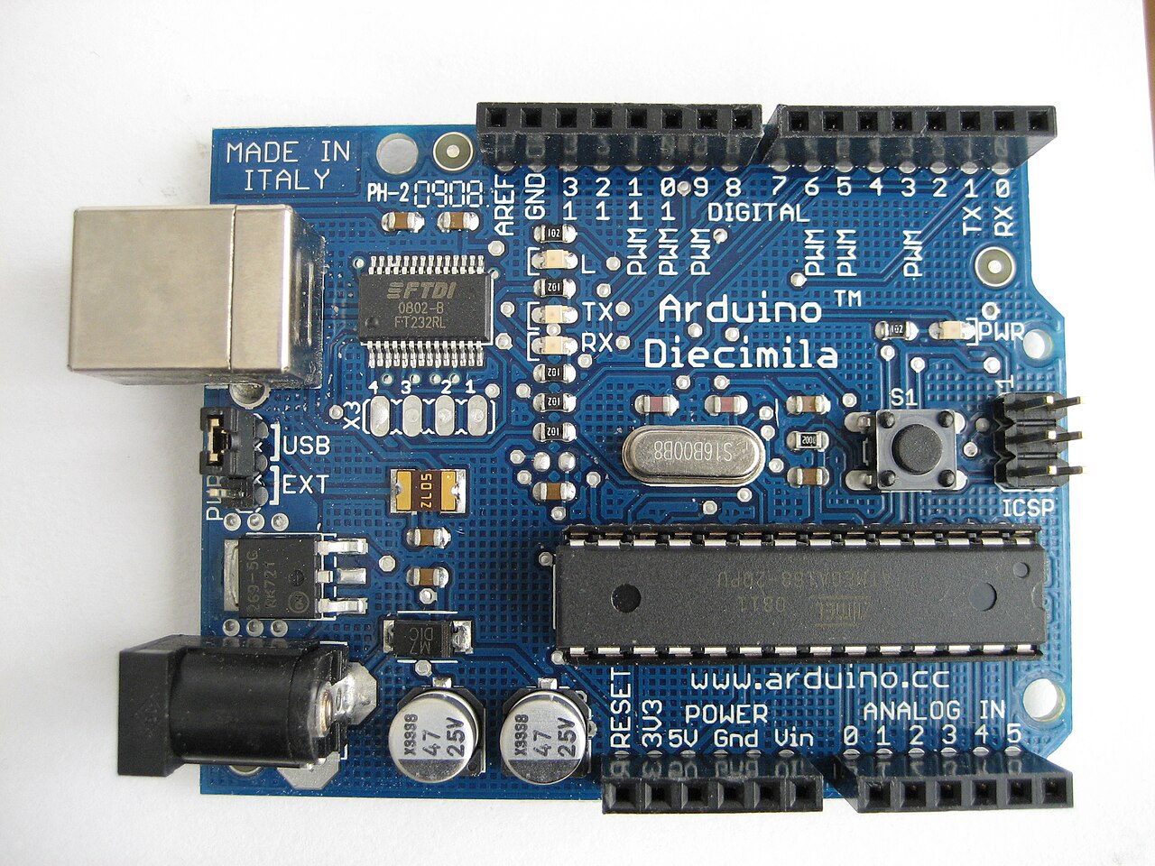
Pinout diagram
| Attr | Specs | verified |
|---|---|---|
mcu | Atmel/Microchip ATmega32u4 — 8-bit AVR RISC, single core, 16 MHz crystal (build.f_cpu=16000000L), with integrated USB 2.0 full-speed device transceiver (no USB-serial chip) (boards.txt, Microchip, datasheet PDF). | ✔ |
gpu | none. | ? unverified |
memory | Flash 32 KB (4 KB bootloader → 28,672 B sketch space, upload.maximum_size=28672); SRAM 2.5 KB (2560 B, upload.maximum_data_size=2560); EEPROM 1 KB (EEPROM library). | ? unverified |
usb | micro-USB connector, native CDC virtual COM port; can also enumerate as keyboard/mouse (HID). IDs: VID 0x2341, PID 0x803C (sketch) / 0x003C (bootloader); legacy VID 0x2A03 also matched (boards.txt). | ✔ |
operating_voltage | 5 V logic (tech specs table, retired page). | ✔ |
power | the official page describes powering the board by connecting it to a computer with a USB cable; a resettable polyfuse (~500 mA) protects the host USB port (retired page, "USB Overcurrent Protection"). No barrel jack or Vin/GND power header is documented anywhere on the official page. | ✔ |
onboard_i_o_the_point_of_the_board | — pin map from Esplora.cpp: - Analog joystick (X, Y axes + center push-button). - 4 push-buttons in a diamond (library names SWITCH_DOWN/LEFT/UP/RIGHT), plus the joystick button. - Linear potentiometer slider near the bottom edge. - Microphone (ambient loudness), light sensor (LDR), temperature sensor (°C/°F via library), 3-axis accelerometer (measures the board's relation to gravity). - Buzzer (square-wave / piezo) on D6 via tone. - Bright RGB LED: red D5, green D10, blue D9 (PWM). - 2 TinkerKit analog inputs + 2 TinkerKit PWM outputs (3-pin connectors for TinkerKit sensor/actuator modules). - TFT display socket for the optional color LCD or other SPI devices (retired page, library properties). - LEDs: ON (green, power), L (yellow, pin 13), RX/TX (yellow, USB activity); reset push-button top-left (retired page). | ✔ |
how_the_sensors_are_wired_critical_for_gpio_planning | — from Esplora.cpp: - A 4-channel analog multiplexer routes 10 sensor channels (4 buttons, slider, light, temperature, microphone, TinkerKit A/B, joystick switch/X/Y — 13 logical channels, MAX_CHANNELS=13) onto one ADC input, A4 (MUX_COM_PIN); the channel is selected by address pins A0, A1, A2, A3 (MUX_ADDR_PINS). - The accelerometer bypasses the mux: X = A5, Y = A11, Z = A6 (zero-g offsets coded as 320/330/310). - Consequence: A0–A6 and A11 are consumed; the only freely documented external outputs are D3 and D11 ("External outputs: D3, D11" comment in Esplora.cpp); D5/D6/D9/D10 and D13 are used by RGB/buzzer/LED. - ADC resolution 10-bit (0–1023); no DAC. UART (TTL Serial1), I2C and SPI exist on the ATmega32u4 but SPI is mainly brought out on the TFT socket; there are no standard Arduino shield headers. | ✔ |
mechanicals | 164.04 × 60 mm, 53 g (max length/width 6.5 × 2.4 in with connectors overhanging); four screw holes (retired page tech specs). | ✔ |
- Manufacturer: Arduino S.r.l. (Italy) — official (now retired) product page in Arduino's docs archive: docs.arduino.cc/retired/boards/arduino-esplora/, source file content.md in arduino/docs-content.
- Product: The Arduino Esplora is a microcontroller board derived from the Arduino Leonardo (same ATmega32u4, same core variant) whose distinguishing trait is a built-in, ready-to-use set of sensors and actuators — joystick, buttons, slider, light/temperature/microphone/accelerometer sensors, buzzer and RGB LED — designed "for people who want to get up and running with Arduino without having to learn about the electronics first" (retired product page, retrieved 2026-10-13). The layout deliberately recalls a game console controller: analog joystick on the left, four push-buttons in a diamond on the right (same page).
- Year: 2012. The official Esplora library source is copyrighted "Copyright (c) 2012 Arduino LLC" (Esplora.h).
- Launch price:
- Status: End-of-life / retired. The board lives under the "retired" section of Arduino's documentation (retired boards page) and the store URL returns 404 as of 2026-10-13 (verified by direct request). The ATmega32u4 itself is "In Production" at Microchip (Microchip product page, retrieved 2026-10-13).
- SKU / variants: single SKU A000095 (front-matter of content.md). No official Esplora revisions are documented. Accessory: an optional color TFT LCD screen that plugged into the board's TFT socket (mentioned on the retired product page).
+ Strengths
- The "toy" board — sensors built in: first Arduino with a ready-to-use onboard sensor suite (joystick, slider, buttons, light, temperature, microphone, accelerometer) and outputs (buzzer, RGB LED), so interaction projects need zero wiring and no electronics knowledge (retired page).
- Gamepad ergonomics: board shape and control placement recall a classic game controller — it became the go-to Arduino for DIY game controllers and wearable "wearable technology" classes (retired page).
- Native USB HID: like the Leonardo it can act as a keyboard and mouse to the host computer while keeping a CDC serial port, using the Keyboard/Mouse libraries — the basis of the official EsploraKart and EsploraRemote projects (retired page, "Communication").
- High-level sensor library: the official Esplora library (Esplora.readSlider, readTemperature(DEGREES_C), writeRGB(r,g,b), tone(f), readAccelerometer(X_AXIS)…) returns pre-processed values (e.g. degrees Celsius) instead of raw ADC (library repo, library docs page).
- Expandability without shields: 2 TinkerKit inputs + 2 TinkerKit outputs (3-pin color-coded modules) and a socket for the official color TFT LCD / any SPI device (retired page, library.properties).
- Open hardware: full EAGLE reference design and schematic published: reference design ZIP, schematic PDF (both verified live 2026-10-13).
− Weaknesses
- Joystick switch has no pull-up resistor — the official library carries an explicit "workaround to cope with lack of pullup resistor on joystick switch" that bit-bangs INPUT_PULLUP on the mux common line only when reading that channel (Esplora.cpp).
- Single shared ADC via multiplexer: all muxed sensors hang off A4 with A0–A3 as address lines; channels must be read sequentially, a channel needs settling time after switching, and you cannot sample two muxed sensors simultaneously or use A0–A4 for anything else (retired page, "Input and Output", Esplora.cpp).
- Very little free GPIO: A0–A6, A11, D5, D6, D9, D10, D13 are consumed by onboard hardware; the library comments expose only D3 and D11 as external outputs (Esplora.cpp). Classic shields don't fit (no headers, gamepad shape).
- Temperature reading is coarse: the library converts with integer math (raw*500/1024)-50 °C — ~0.5 °C quantization and formula-specific scaling; it is an approximation of the analog temperature sensor's curve, not a calibrated measurement (Esplora.cpp).
- Accelerometer zero offsets are hard-coded per axis (320/330/310) — unit-to-unit variation means readings drift; recalibrate for your board (Esplora.cpp).
- Leonardo-class USB behavior: Serial is the USB CDC port, not pins 0/1; a bad sketch that hangs at boot can re-grab the bus on every plug-in — recover by pressing reset and uploading within the ~8 s bootloader window, or trigger the bootloader via the 1200-baud touch (retired page, boards.txt). HID sketches that move the host mouse/keyboard can make the PC unusable until re-flash (same class of issue officially warned about for the Leonardo, Leonardo tech-specs note).
- USB-only power: official docs describe only USB powering; battery projects need a USB power source (power bank / LiPo boost cable) since no power jack is documented (see SoC & specs note).
- EOL support: no longer sold (store 404, 2026-10-13) and docs are frozen in the retired section; hardware support now runs through Arduino support and the Esplora forum board.
- Retour d'expérience expert expert — expert-arduino
- Petit retour sur l'Esplora maintenant qu'elle est officiellement retiree. La fiche confirme ce qu'on savait : c'est une base Leonardo (ATmega32u4) bourree de capteurs pre-soudes, ideale pour debuter sans souder un fil. Le point fort reste la librairie Esplora qui renvoie des valeurs propres (degree… — expert-arduino
- Merci pour le resume. Je viens de récupérer une Esplora en seconde main pour un projet de manette retro. Tu mentionnes les problèmes de GPIO, mais c'est vraiment aussi restrictif que la doc le dit ? J'ai lu que seuls D3 et D11 etaient libres pour sortir. Si je veux ajouter un petit affichage OLED, … — maker-debutant-88
- Pour repondre a maker-debutant, oui, D3 et D11 sont les seules sorties 'faciles' exposees par la lib, le reste est cannibalise par les capteurs internes ou le mux. Pour l'OLED, si tu passes par le port TFT (SPI), ca marche mais tu perds la compatibilite avec l'ecran officiel couleur si tu prevois d… — tech-hacker-01
Community feedback and projects
- Menu principal sur un jeu Snake carte Esplora forum.arduino.cc
- Connect arduino esplora to microstep driver forum.arduino.cc
- problema con Esplora e TFT, scrivere su microSD forum.arduino.cc
- How to use the Esplora as a controller for the Wii (SSBB) forum.arduino.cc
- Interfacing Parallax Gyroscope Module 3-Axis L3G4200D (SPI) to Esplora? forum.arduino.cc
- ATmega16U4/32U4 datasheet PDF (Microchip) datasheet
- EAGLE reference design ZIP other
- schematic PDF schematic
- EAGLE reference design ZIP other
- Joystick switch has no pull-up resistor — the official library carries an explicit "workaround to cope with lack of pullup resistor on joystick switch" that bit-bangs INPUT_PULLUP on the mux common line only when reading that channel (Esplora.cpp).
- Single shared ADC via multiplexer: all muxed sensors hang off A4 with A0–A3 as address lines; channels must be read sequentially, a channel needs settling time after switching, and you cannot sample two muxed sensors simultaneously or use A0–A4 for anything else (retired page, "Input and Output", Esplora.cpp).
- Very little free GPIO: A0–A6, A11, D5, D6, D9, D10, D13 are consumed by onboard hardware; the library comments expose only D3 and D11 as external outputs (Esplora.cpp). Classic shields don't fit (no headers, gamepad shape).
- Temperature reading is coarse: the library converts with integer math (raw*500/1024)-50 °C — ~0.5 °C quantization and formula-specific scaling; it is an approximation of the analog temperature sensor's curve, not a calibrated measurement (Esplora.cpp).
- Accelerometer zero offsets are hard-coded per axis (320/330/310) — unit-to-unit variation means readings drift; recalibrate for your board (Esplora.cpp).
- Leonardo-class USB behavior: Serial is the USB CDC port, not pins 0/1; a bad sketch that hangs at boot can re-grab the bus on every plug-in — recover by pressing reset and uploading within the ~8 s bootloader window, or trigger the bootloader via the 1200-baud touch (retired page, boards.txt). HID sketches that move the host mouse/keyboard can make the PC unusable until re-flash (same class of issue officially warned about for the Leonardo, Leonardo tech-specs note).
- USB-only power: official docs describe only USB powering; battery projects need a USB power source (power bank / LiPo boost cable) since no power jack is documented (see SoC & specs note).
- EOL support: no longer sold (store 404, 2026-10-13) and docs are frozen in the retired section; hardware support now runs through Arduino support and the Esplora forum board.
- Faire clignoter la LED RGB de l'Esplora debutant Schéma : IMG-esplora-debutant-1-esplora-clignotement-rgb.svg — Vue de dessus d'une Arduino Esplora avec la LED RGB mise en évidence et les broches internes D5 (rouge), D10 (verte) et D9 (bleue) annotées.
- Les 4 boutons du pavé comme sélecteurs de couleur debutant Schéma : IMG-esplora-debutant-2-esplora-boutons-couleurs.svg — Manette Esplora avec les quatre boutons en losange (SWITCH_UP, DOWN, LEFT, RIGHT) surlignés et flèches vers la LED RVB.
- Console série : afficher les capteurs embarqués debutant Schéma : IMG-esplora-debutant-3-esplora-console-serie-capteurs.svg — Esplora reliée par câble USB à un ordinateur affichant le moniteur série avec slider, lumière, température et accéléromètre.
- Capteur de lumière avec seuil et hystérésis intermediaire Schéma : IMG-esplora-intermediaire-1-esplora-capteur-lumiere-hysteresis.svg — Courbe d'hystérésis superposée à l'Esplora, avec la LED RVB verte en mode jour et rouge en mode nuit et les deux seuils annotés.
- Transformer l'Esplora en clavier USB (HID) intermediaire Schéma : IMG-esplora-intermediaire-2-esplora-hid-clavier.svg — Esplora représentée en train de taper dans un champ de texte d'un ordinateur via les bibliothèques Keyboard, boutons du losange reliés aux touches A/S/D/F.
- Piloter un micro-servo avec le joystick intermediaire Schéma : IMG-esplora-intermediaire-3-esplora-servo-joystick.svg — Esplora vue de dessus, joystick à gauche, câble vers un micro-servo branché sur la sortie externe D3 avec alimentation et masse annotées.
- Registres AVR et interruption timer : échantillonner le multiplexeur avance Schéma : IMG-esplora-avance-1-esplora-registres-interruption-timer.svg — Schéma fonctionnel du multiplexeur 4 vers 1 de l'Esplora : broches A0-A3 en adresse, A4 en ADC commun, canaux boutons/slider/lumière/température/son, avec le timer TCNT2 en horloge.
- Télécommande HID avancée : clavier + souris + série simultanés avance Schéma : IMG-esplora-avance-2-esplora-hid-avance-telecommande.svg — Esplora au centre émettant trois flux USB vers l'ordinateur : clavier HID, souris HID et port série CDC, avec joystick pilotant le curseur et boutons les touches.
- Mode basse consommation : sleep profond et watchdog avance Schéma : IMG-esplora-avance-3-esplora-low-power-watchdog.svg — Chronogramme du cycle de veille de l'Esplora : réveil par watchdog 1 s, lecture du capteur de température, décision buzzer, retour en power-down, avec le régulateur USB annoté.
Code library — examples written for this board
joystick-couleur.inoArduinojeu-boutons.inoArduinoslider-luminosite.inoArduinothermometre-couleur.inoArduinosonometre.inoArduinoaccelerometre-tilt.inoArduinoboite-musique.inoArduinojoystick-souris.inoArduinotinkerkit.inoArduinoveilleuse-automatique.inoArduino
Examples and repos found online
- arduino-libraries/Esplora github.com
- arduino/ArduinoCore-avr github.com
- TheKitty/EsploraApps github.com
- Bismuth208/Firecore github.com
- MrYsLab/esp4s github.com