ESP8266 (ESP-12E module)
⚡ The essentials in 60 seconds
- soc_mcu — ESP8266EX, single-core Tensilica L106 (Diamond Standard 106Micro) 32-bit RISC, 80 MHz default, up to 160 MHz (
- cpu — 1 core, ~80% of processing power left free for the user after the Wi-Fi RTOS stack (Espressif product page). No GPU.
- memory — 160 KB total RAM: 32 KB instruction RAM (iRAM), 32 KB instruction cache, 96 KB dRAM (80 KB usable for SDK+heap, 16 KB ROM-mapped) (
- storage — external QSPI flash, 512 KB–4 MB typical, up to 16 MB supported; ESP-12E ships with 4 MB ( No filesystem in silicon — use SPIFFS/LittleFS on flash.
- connectivity — Wi-Fi 802.11 b/g/n 2.4 GHz only (no Bluetooth, no Ethernet). On-chip TR switch, balun, LNA, PA and matching network ( ESP-12E: PCB-trace antenna + external antenna footprint.
- gpio — 17 GPIOs on the chip; fewer exposed on boards. Peripherals: SPI, I2C (software/bit-banged only), I2S with DMA, UART (plus TX-only UART on GPIO2), 10-bit SAR ADC on a single pin (ADC0/A0) ( - GPIO6–GPIO11 are wired to the flash chip — never use them ( - GPIO16: no interrupt, no PWM, no I2C; used for deep-sleep wake (wired to RST). - PWM is software (R-WS2812/ESP8266WiFi-based analogWrite), 1 effective channel family via ESP8266PWM.
- On this board : 9 tutorials · 10 code
The ESP8266, specifically in the form of the ESP-12E module, stands as a pivotal component in the history of modern electronics, marking the moment when Wi-Fi connectivity became accessible to hobbyists and engineers at an unprecedentedly low cost. While the core silicon, the ESP8266EX, was designed by Espressif Systems, the ESP-12E itself is a third-party module design created by Ai-Thinker, the same vendor that popularized the chip with the earlier ESP-01 module in August 2014. Although the exact release month of the ESP-12E remains unverified due to Ai-Thinker’s lack of a public changelog, the module family appeared around 2015 and quickly became a standard in maker communities. Today, the chip is considered active but legacy, as Espressif has officially superseded it with the more powerful ESP32 family, yet it remains widely available and supported for projects that do not require advanced features like Bluetooth or dual-core processing.
At the heart of the ESP-12E is a single-core Tensilica L106 processor, a 32-bit RISC architecture that operates at a default frequency of 80 MHz, with the capability to overclock up to 160 MHz. It is crucial to understand that this is not a general-purpose computer in the traditional sense; the processor shares its resources with the Wi-Fi stack. Approximately 80 percent of the processing power is reserved for handling network communications, leaving the remaining capacity for user applications. The memory architecture is equally constrained, featuring 160 KB of total RAM. This is divided into instruction RAM, instruction cache, and data RAM, with only about 80 KB of heap memory usable for user code and dynamic data storage. There is no internal storage for user files; instead, the module relies on external QSPI flash memory. The ESP-12E typically ships with 4 MB of flash, though clones and older variants may have as little as 512 KB. Since there is no native file system in silicon, developers must use software solutions like SPIFFS or LittleFS to manage data storage on the flash chip.
Connectivity is the primary strength of this module, supporting Wi-Fi 802.11 b/g/n on the 2.4 GHz band. It does not support Bluetooth or Ethernet. The RF front-end is fully integrated on the chip, including the power amplifier, low-noise amplifier, and matching network, which allows the module to function with minimal external components. The ESP-12E features a PCB-trace antenna and a footprint for an external antenna, providing flexibility in design. However, this high level of integration comes with strict power requirements. The module operates on a 3.3 V logic level and is not tolerant of 5 V signals. During Wi-Fi transmission bursts, the current draw can spike sharply, requiring a power supply capable of delivering peaks of 300 to 500 mA. If the power rail cannot support these peaks, the module will suffer from brownout resets, a common source of frustration for beginners. This is often characterized by garbled serial output and unexpected reboots, which can be mitigated by using a robust 3.3 V regulator and bulk capacitance.
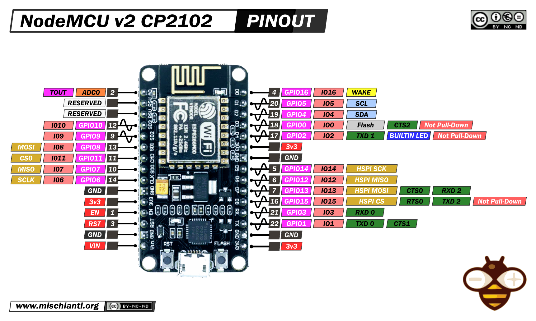
The input/output capabilities of the ESP-12E are limited compared to more modern microcontrollers, and understanding the specific quirks of its GPIO pins is essential for successful development. The chip offers 17 GPIOs, but not all are available for general use. Pins GPIO6 through GPIO11 are internally wired to the flash memory and must never be used, as doing so will corrupt the program execution. GPIO16 is special; it lacks interrupt, PWM, and I2C capabilities but is wired to the reset pin, making it critical for waking the device from deep sleep. Other pins, such as GPIO0, GPIO2, and GPIO15, have boot-level sensitivities. For instance, GPIO15 must be held low at boot, while GPIO0 and GPIO2 must be high. Incorrect wiring of these pins can prevent the module from starting up. Furthermore, the ESP8266 lacks hardware I2C support, meaning that I2C communication must be "bit-banged" in software, which consumes CPU cycles and struggles with high speeds or heavy Wi-Fi loads. Similarly, PWM is implemented via software, limiting the number of effective channels.
One of the most significant pitfalls for new users is the analog-to-digital converter (ADC). The ESP8266 has only one ADC pin (ADC0/A0), and on the bare ESP-12E module, it reads voltages from 0 to 1.0 V, not the full 3.3 V range. Many development boards, like the NodeMCU, include an onboard voltage divider to scale this up, but the bare module does not. Assuming a 3.3 V full-scale reading on a bare ESP-12E will result in incorrect data. Additionally, the ADC is known for nonlinearity and noise, partly because it shares circuitry with the Wi-Fi RF components. Developers must also be aware of the software watchdog timer in the Arduino core, which resets the chip if the main loop is blocked for more than six seconds. Long-running operations require periodic calls to yield or ESP.wdtFeed to keep the system alive.
Despite these limitations, the ESP8266 ecosystem is vast and vibrant. The module is supported by several official SDKs from Espressif, including a non-OS SDK and an RTOS SDK based on FreeRTOS. However, the de facto standard for most makers is the Arduino core, which allows for rapid prototyping using familiar C++ syntax. Alternative runtimes include MicroPython, Lua via NodeMCU firmware, and various community-driven platforms like ESPHome, Tasmota, and ESP-Easy. These firmware solutions have turned the ESP8266 into the backbone of many DIY smart home projects, allowing users to flash pre-built software onto smart plugs and bulbs to make them hackable and controllable via local networks. Flashing new code is typically done via a serial bootloader using UART0, often facilitated by USB-to-serial bridges like the CP2102 or CH340. Over-the-air (OTA) updates over Wi-Fi are also supported, adding convenience for deployed devices.
In summary, the ESP-12E is a minimalist yet powerful tool for adding Wi-Fi to embedded projects. It is defined by its constraints: a single core, limited RAM, no hardware I2C, and a single noisy ADC pin. However, its low cost, mature software ecosystem, and integrated RF design make it an enduring choice for battery-powered sensors, IoT nodes, and educational projects. While it has been superseded by the ESP32 for high-performance applications, the ESP8266 remains a cornerstone of the maker community, offering a gentle introduction to the complexities of connected devices, provided the user respects its specific electrical and logical requirements.
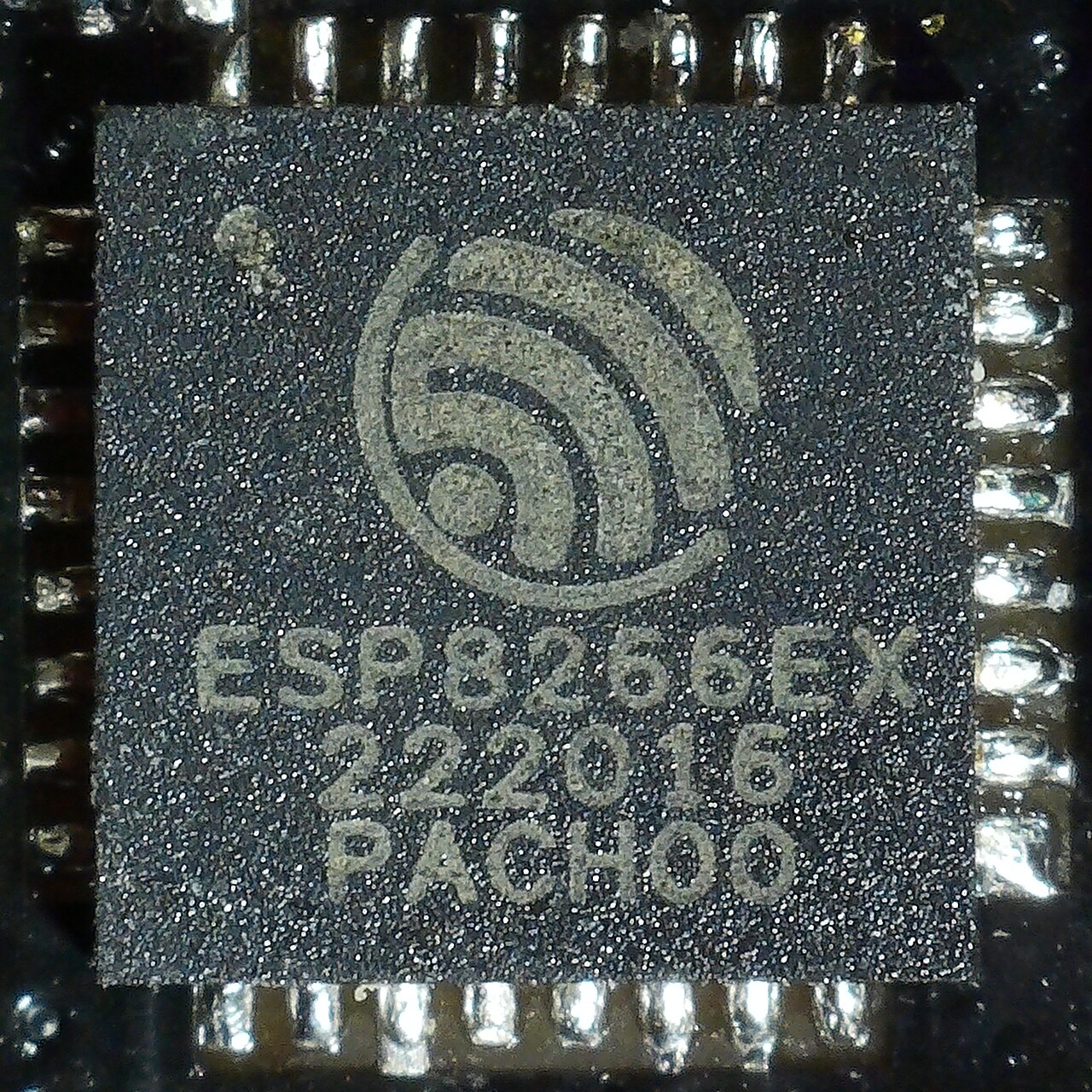
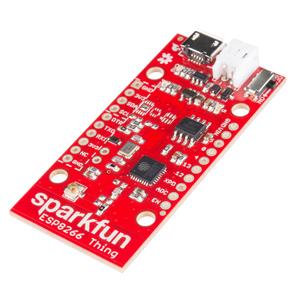
Pinout diagram
| Attr | Specs | verified |
|---|---|---|
soc_mcu | ESP8266EX, single-core Tensilica L106 (Diamond Standard 106Micro) 32-bit RISC, 80 MHz default, up to 160 MHz ( | ✔ |
cpu | 1 core, ~80% of processing power left free for the user after the Wi-Fi RTOS stack (Espressif product page). No GPU. | ? unverified |
memory | 160 KB total RAM: 32 KB instruction RAM (iRAM), 32 KB instruction cache, 96 KB dRAM (80 KB usable for SDK+heap, 16 KB ROM-mapped) ( | ✔ |
storage | external QSPI flash, 512 KB–4 MB typical, up to 16 MB supported; ESP-12E ships with 4 MB ( No filesystem in silicon — use SPIFFS/LittleFS on flash. | ✔ |
connectivity | Wi-Fi 802.11 b/g/n 2.4 GHz only (no Bluetooth, no Ethernet). On-chip TR switch, balun, LNA, PA and matching network ( ESP-12E: PCB-trace antenna + external antenna footprint. | ✔ |
gpio | 17 GPIOs on the chip; fewer exposed on boards. Peripherals: SPI, I2C (software/bit-banged only), I2S with DMA, UART (plus TX-only UART on GPIO2), 10-bit SAR ADC on a single pin (ADC0/A0) ( - GPIO6–GPIO11 are wired to the flash chip — never use them ( - GPIO16: no interrupt, no PWM, no I2C; used for deep-sleep wake (wired to RST). - PWM is software (R-WS2812/ESP8266WiFi-based analogWrite), 1 effective channel family via ESP8266PWM. | ✔ |
logic_level | 3.3 V only, VCC up to 3.6 V; NOT 5 V tolerant ( | ✔ |
power | 3.3 V DC, typically 3.0–3.6 V; deep-sleep mode in the tens of µA range, three power modes (active/sleep/deep-sleep) ( > | ✔ |
tx_current_caveat | Wi-Fi transmit bursts can pull sharp current peaks; designs need a 3.3 V rail able to supply ≥ 300–500 mA peaks or brownout resets occur (widely documented; see the ESP8266 Arduino core docs, | ✔ |
temperature | industrial range advertised by Espressif ("wide operating temperature range"); exact grade depends on module. > | ? unverified |
- Manufacturer: SoC by Espressif Systems (Shanghai); the ESP-12E module is a third-party design by Ai-Thinker, the same vendor that popularized the ESP8266 with the ESP-01 in August 2014 (source:
- SoC: ESP8266EX (the "EX" revision; earlier boards used ESP8266/ESP8266EX variants).
- Year: chip launched 2014; ESP8266EX and ESP-12-family modules appeared around 2015. >
- Status: Active/legacy-active. Espressif still lists the ESP8266EX as a current product ( but it is officially superseded by the ESP32 family (
- Launch price: ESP8266EX was launched as an aggressively low-cost Wi-Fi chip; ESP-12E modules have typically sold for ≈ US$2–3 in single quantities (retail street price, not an official RRP). >
- Variants: module family ESP-12 / 12E / 12F (Ai-Thinker, mostly 4 MB flash), Espressif's own ESP-WROOM-02/02D/02U/S2 modules ( and dev boards: NodeMCU v1/v2/v3 (ESP-12E), Wemos D1 Mini, ESP-01/01S (
+ Strengths
- First ultra-cheap "Wi-Fi + MCU in one chip" — the device that created the modern ESP maker ecosystem (
- Fully integrated RF front-end (PA, LNA, balun, filters) → works with almost no external components, tiny PCB footprint (
- Huge community firmware ecosystem: Tasmota, ESPHome, ESP-Easy turn relays/plugs into hackable IoT devices (
- Deep sleep with RTC timer + GPIO16 external wake — viable battery sensors (
- Limitations that define it: single analog pin, no Bluetooth, no hardware I2C, single core, 80 KB heap — it is the "minimal" ESP.
− Weaknesses
- Brownout detector resets: weak 3.3 V supplies (PC FTDI pins, cheap LDOs) cause the famous c0 3 3 3... / "cck" garbage and rd RST brownout reboots during Wi-Fi TX; fix with a proper ≥500 mA 3.3 V supply and bulk capacitance (
- ADC is 0–1.0 V on the bare chip (not 0–3.3 V); NodeMCU boards add an onboard divider, ESP-12E bare modules do not — readings are wrong if you assume 3.3 V full-scale; the ADC is also nonlinearity/noisy and shares its pin with Wi-Fi RF circuitry (
- Boot-state GPIO surprises: GPIO15 must be LOW to boot (ESP-12E has a 10k pull-down), GPIO0/GPIO2 must be HIGH; loading GPIO1/3 (UART) or GPIO2 at boot prevents boot; GPIO16/1/3/9/10 go HIGH at boot — relays glitch (
- GPIO6–11 reserved for flash: using them corrupts execution — a classic beginner brick (
- Watchdog resets: the Arduino core's software watchdog (WDT) resets code that blocks the loop for > ~6 s; long operations need yield/ESP.wdtFeed (
- No hardware I2C: bit-banged I2C costs CPU and struggles above 100 kHz with interrupts-heavy Wi-Fi load (
- Flash-size confusion: ESP-12E vs ESP-12 vs clones: 512 KB vs 4 MB flash sold under the same name; wrong board selection → boot loops (
- Retour d'expérience expert expert — expert-microcontroleur
- Petit retour d'experience sur l'ESP-12E après quelques mois d'utilisation. Le prix reste imbattable pour du Wi-Fi embarque, mais attention aux pieges classiques. Les brownouts sont monnaie courante si votre alimentation 3.3V n'est pas solide : j'ai eu des reboots aléatoires (les fameux c0 3 3 3) av… — expert-microcontroleur
- Merci pour ces precisions ! Je bute justement sur un souci de boot loop. J'ai configure mon IDE pour le module ESP-12E, mais le code ne démarre pas. Je suspecte un problème de taille de flash car j'ai lu que certaines variantes 12E sont vendues avec seulement 512Ko alors que d'autres ont 4Mo. Comme… — maker_novice
- Pour l'ADC, oui, un diviseur externe est indispensable sur le module nu si ton signal depasse 1V. Pour la flash, verifie bien le marquage sur la puce, mais souvent le choix du board dans Arduino IDE suffit si tu as la bonne taille. Attention aussi au GPIO15 : il doit être a l'état bas (LOW) pour dé… — bricoleur_solitaire
Community feedback and projects
- NodeMCU ESP-12e - Timing errors arduino.stackexchange.com
- ESP8266-12E unstable WiFi connection (Need feedback) electronics.stackexchange.com
- Self-built ESP-12E Module not connecting to PC forum.arduino.cc
- LAMEBOY - another ESP12 handheld hackaday.io
Content not available yet.
- Brownout detector resets: weak 3.3 V supplies (PC FTDI pins, cheap LDOs) cause the famous c0 3 3 3... / "cck" garbage and rd RST brownout reboots during Wi-Fi TX; fix with a proper ≥500 mA 3.3 V supply and bulk capacitance (
- ADC is 0–1.0 V on the bare chip (not 0–3.3 V); NodeMCU boards add an onboard divider, ESP-12E bare modules do not — readings are wrong if you assume 3.3 V full-scale; the ADC is also nonlinearity/noisy and shares its pin with Wi-Fi RF circuitry (
- Boot-state GPIO surprises: GPIO15 must be LOW to boot (ESP-12E has a 10k pull-down), GPIO0/GPIO2 must be HIGH; loading GPIO1/3 (UART) or GPIO2 at boot prevents boot; GPIO16/1/3/9/10 go HIGH at boot — relays glitch (
- GPIO6–11 reserved for flash: using them corrupts execution — a classic beginner brick (
- Watchdog resets: the Arduino core's software watchdog (WDT) resets code that blocks the loop for > ~6 s; long operations need yield/ESP.wdtFeed (
- No hardware I2C: bit-banged I2C costs CPU and struggles above 100 kHz with interrupts-heavy Wi-Fi load (
- Flash-size confusion: ESP-12E vs ESP-12 vs clones: 512 KB vs 4 MB flash sold under the same name; wrong board selection → boot loops (
- Faire clignoter une LED avec l'ESP8266-ESP-12E debutant Schéma : IMG-esp8266-esp-12e-debutant-1-esp8266-blink-led.svg — Carte ESP8266-ESP-12E alimentée en 3,3 V, LED avec résistance sur GPIO2, broches CH_PD et VCC câblées.
- Lire un bouton sur GPIO4 avec l'ESP8266-ESP-12E debutant Schéma : IMG-esp8266-esp-12e-debutant-2-esp8266-bouton-gpio4.svg — Module ESP8266-ESP-12E, bouton poussoir entre GPIO4 et la masse, résistance de pull-up interne activée, console UART0 sur GPIO1/GPIO3.
- Lire une tension avec l'ADC A0 et un diviseur de tension debutant Schéma : IMG-esp8266-esp-12e-debutant-3-esp8266-adc-a0-diviseur.svg — Module ESP8266-ESP-12E nu, diviseur de tension R1 20 kΩ / R2 10 kΩ ramenant une tension 0–3,3 V dans la plage 0–1,0 V de la broche A0.
- Se connecter au Wi-Fi en mode station et suivre le RSSI intermediaire Schéma : IMG-esp8266-esp-12e-intermediaire-1-esp8266-wifi-sta-rssi.svg — Module ESP8266-ESP-12E relié à un point d'accès Wi-Fi 2,4 GHz, antenne PCB, condensateur de découplage sur le rail 3,3 V, console série sur UART0.
- Serveur web de commande d'une LED en MicroPython intermediaire Schéma : IMG-esp8266-esp-12e-intermediaire-2-esp8266-serveur-web-led.svg — Module ESP-12E exécutant MicroPython, LED embarquée sur GPIO2 (active-LOW), connecté au réseau local, navigateur d'un ordinateur ou smartphone sur le même réseau.
- Publier et s'abonner en MQTT avec PubSubClient intermediaire Schéma : IMG-esp8266-esp-12e-intermediaire-3-esp8266-mqtt-pubsub.svg — Module ESP8266-ESP-12E connecté via Wi-Fi à un broker MQTT sur le réseau local, échanges sur les sujets esp12e/rssi et esp12e/led, LED sur GPIO2.
- Deep sleep sur batterie avec réveil par GPIO16 avance Schéma : IMG-esp8266-esp-12e-avance-1-esp8266-deep-sleep-batterie.svg — Module ESP-12E alimenté par régulateur LDO sur batterie LiPo, fil GPIO16 relié à RST pour le réveil, LED de test déconnectée, bouton de réveil externe optionnel.
- Programmation OTA : téléverser le code par Wi-Fi avance Schéma : IMG-esp8266-esp-12e-avance-2-esp8266-ota-arduino.svg — Module ESP8266-ESP-12E flashé une première fois par câble série puis mis à jour par Wi-Fi depuis un ordinateur, routeur en point d'accès, flash 4 Mo du module annotée.
- Gérer la flash 4 Mo : partitions et LittleFS avance Schéma : IMG-esp8266-esp-12e-avance-3-esp8266-partitions-littlefs.svg — Répartition de la flash 4 Mo d'un module ESP-12E : bootloader, deux slots de sketch OTA, NVS et partition LittleFS, avec le câble série branché pour le premier flashage.
Code library — examples written for this board
clignotante.inoArduinobouton-led.inoArduinorespiration.inoArduinodht11.inoArduinoluxmetre.inoArduinoserveur-web.inoArduinosommeil-profond.inoArduinoservo.inoArduinows2812.inoArduinocapteur_web.pyMicroPython
Examples and repos found online
- esp8266/Arduino github.com
- arendst/Tasmota github.com
- esphome/esphome github.com