ESP32 (original, ESP32-WROOM-32 class)
⚡ The essentials in 60 seconds
- cpu — dual-core Tensilica Xtensa LX6 @ up to 240 MHz (80/160/240 MHz selectable), plus a ULP协processor on the RTC domain; 520 KB SRAM + 16 KB RTC SRAM, 448 KB ROM (
- gpu — none.
- storage — external SPI flash, typically 4 MB (WROOM-32), up to 16 MB; WROVER adds 4–8 MB PSRAM (
- connectivity — Wi-Fi 802.11 b/g/n 2.4 GHz (150 Mbps HT40) + Bluetooth Classic + BLE 4.2; Ethernet (external PHY), CAN 2.0, SDIO, 10/100 MAC ( ESP-IDF docs
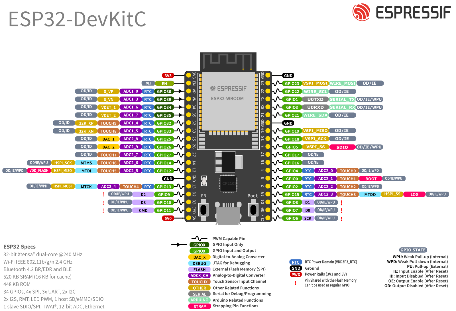
- gpio — 34 usable GPIOs (GPIO34–39 input-only, no pull-ups; GPIO6–11 strapping/flash on older modules — treat as unavailable). Peripherals: 3× SPI, 3× UART, 2× I2C, 1× I2S, SDMMC, 16× LEDC PWM channels (8-bit duty, up to 40 MHz), RMT (8 TX/8 RX), 2× 8-bit DAC (GPIO25/26), touch sensing (10 pads), hall sensor, 12-bit ADC (18 external channels across ADC1/ADC2; ADC2 is unusable while Wi-Fi runs) (ESP32 datasheet ESP-IDF API docs
- logic_level — 3.3 v
- On this board : 9 tutorials · 10 code
The ESP32 stands as one of the most influential microcontrollers in the history of embedded electronics, a chip that fundamentally lowered the barrier to entry for wireless connectivity in hobbyist and industrial projects alike. Released in September 2016 by Espressif Systems, this dual-core system-on-chip (SoC) was manufactured by TSMC on a 40-nanometer process, a technology node that allowed for high performance at a remarkably low cost. At its heart lies two Tensilica Xtensa LX6 processors, which can operate at clock speeds of 80, 160, or 240 megahertz. To understand what this means for a developer, consider that the clock speed determines how many instructions the processor can execute per second; 240 MHz is more than sufficient for handling complex logic, sensor data processing, and even driving displays, while the dual-core architecture allows for true parallel processing. This means the chip can dedicate one core to maintaining a stable Wi-Fi or Bluetooth connection while the other core runs your application code, preventing the system from freezing when network traffic spikes. The chip includes 520 kilobytes of static random-access memory (SRAM), which is volatile memory used for fast data access during operation, and 16 kilobytes of RTC SRAM, which remains powered during deep sleep modes to preserve critical state information. While the ESP32 does not include a graphics processing unit (GPU), its raw processing power is often enough for simple graphical user interfaces on small screens, though it is not designed for heavy graphical rendering.
One of the defining characteristics of the ESP32 is its integrated wireless capabilities, which combine Wi-Fi 802.11 b/g/n on the 2.4 GHz band with both Bluetooth Classic and Bluetooth Low Energy (BLE) 4.2. This combination was revolutionary at launch because it offered a single, low-cost solution for projects that needed both high-throughput data transfer (via Wi-Fi) and low-power device pairing (via BLE). The Wi-Fi capability supports speeds up to 150 Mbps, which is more than adequate for streaming sensor data, serving web pages, or handling video streams from camera modules. The inclusion of Bluetooth Classic allows for legacy device compatibility, such as connecting to older audio systems or keyboards, while BLE enables efficient communication with modern smartphones and wearables. This dual-radio approach is managed by a sophisticated software stack, but it comes with a physical constraint: both radios share a single antenna. Consequently, when both Wi-Fi and Bluetooth are active simultaneously, the overall throughput can decrease, and certain power-saving features may not function as expected. This is a critical consideration for developers designing battery-powered devices that require constant connectivity.
The ESP32 is available in various module configurations, the most common being the ESP32-WROOM-32, which integrates the chip with an external 4 MB SPI flash memory. Flash memory is non-volatile storage, meaning it retains your program code and data even when the power is turned off. Some variants, such as the ESP32-WROVER, add additional Pseudo-Static RAM (PSRAM), typically 4 or 8 MB, which provides a larger working memory pool for memory-intensive applications like image processing or large data buffers. The chip operates on a 3.3-volt logic level and is not tolerant of 5-volt signals, a crucial detail for beginners who might be used to older Arduino boards that accept 5-volt inputs. Connecting a 5-volt sensor directly to an ESP32 pin can permanently damage the chip, so level-shifting circuits are often necessary. Power management is a key strength of the ESP32, offering multiple sleep modes. In deep-sleep mode, the chip can consume as little as 10 microamps, waking up via a timer or external interrupt. This makes it ideal for battery-operated sensors that need to last for months or years on a single charge. However, during active Wi-Fi transmission, the current draw can spike to hundreds of milliamps, requiring a robust 3.3-volt power supply capable of delivering at least 500 milliamps to prevent brownout resets, where the voltage drops too low and the chip restarts unexpectedly.
The input/output capabilities of the ESP32 are extensive, featuring 34 usable general-purpose input/output (GPIO) pins. These pins can be configured for various digital and analog functions. For analog signals, the ESP32 provides a 12-bit analog-to-digital converter (ADC) with 18 external channels, allowing it to read varying voltage levels from sensors like potentiometers or light-dependent resistors. However, a well-known limitation is that the ADC2 pins conflict with the Wi-Fi driver; if Wi-Fi is active, ADC2 reads will return zero, forcing developers to use ADC1 pins (GPIO32–39) for analog sensing in wireless applications. Additionally, the raw ADC readings are known to be nonlinear, particularly at the extremes of the voltage range, so software calibration is often required for accurate measurements. The chip also includes two 8-bit digital-to-analog converters (DACs) on GPIO25 and GPIO26, which can generate analog voltage levels for audio or control signals. For motor control and LED dimming, the ESP32 features 16 LEDC PWM channels, which allow for precise control of power delivery to devices. It also includes unique peripherals such as a hall effect sensor for detecting magnetic fields, capacitive touch sensing on 10 pads, and an RMT peripheral that can generate precise timing signals for driving addressable LEDs like WS2812s without using CPU cycles.
Despite its versatility, the ESP32 has several quirks and limitations that developers must navigate. The pinout can be confusing, with some pins labeled differently on development boards than their internal GPIO numbers, and certain pins (GPIO34–39) being input-only, meaning they cannot output signals or enable pull-up resistors. Furthermore, specific pins known as strapping pins (GPIO0, GPIO2, and GPIO12) determine the boot mode of the chip. If GPIO12 is pulled low at startup on certain module variants, it can prevent the chip from booting correctly, a common source of frustration for newcomers. The on-chip temperature sensor is largely uncalibrated and inaccurate, so it should not be used for precise thermal measurements. Security features, including hardware-accelerated encryption (AES, SHA, RSA) and secure boot, are available, with the ECO V3 silicon revision improving upon earlier bugs and adding support for secure boot v2. The software ecosystem is robust, centered around the ESP-IDF, a comprehensive development framework based on FreeRTOS, which allows for professional-grade application development. For those preferring a simpler approach, the Arduino core for ESP32 provides a familiar interface, while MicroPython and CircuitPython offer scripting capabilities for rapid prototyping. Whether you are building a smart home hub, a wireless sensor network, or a complex IoT gateway, the ESP32 remains a powerful, cost-effective, and highly capable platform that continues to evolve through active community support and official updates.
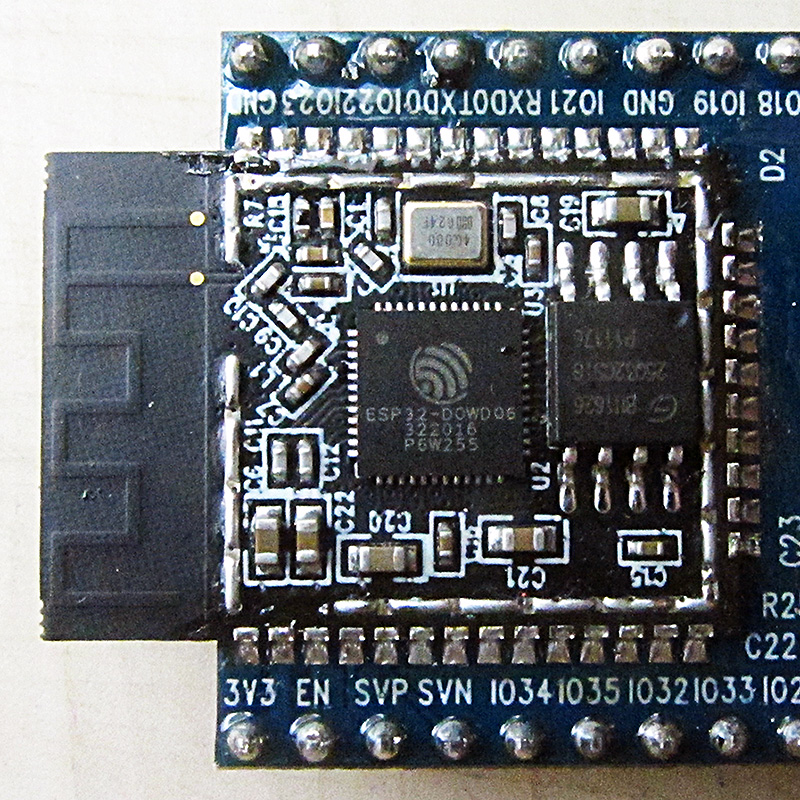
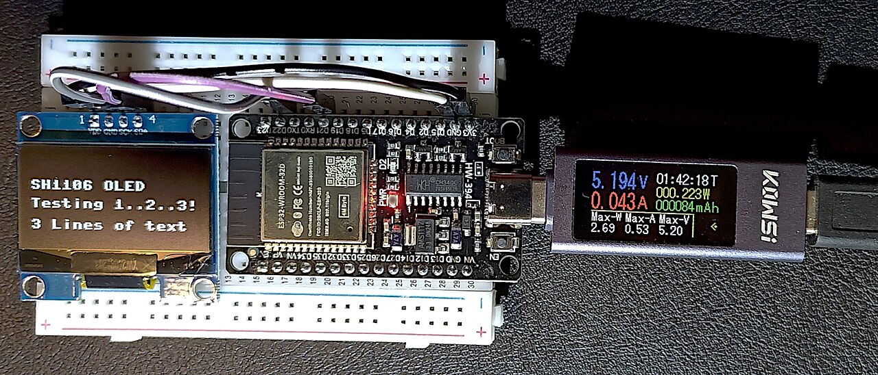
Pinout diagram
| Attr | Specs | verified |
|---|---|---|
cpu | dual-core Tensilica Xtensa LX6 @ up to 240 MHz (80/160/240 MHz selectable), plus a ULP协processor on the RTC domain; 520 KB SRAM + 16 KB RTC SRAM, 448 KB ROM ( | ✔ |
gpu | none. | ? unverified |
storage | external SPI flash, typically 4 MB (WROOM-32), up to 16 MB; WROVER adds 4–8 MB PSRAM ( | ✔ |
connectivity | Wi-Fi 802.11 b/g/n 2.4 GHz (150 Mbps HT40) + Bluetooth Classic + BLE 4.2; Ethernet (external PHY), CAN 2.0, SDIO, 10/100 MAC ( ESP-IDF docs | ✔ |
gpio | 34 usable GPIOs (GPIO34–39 input-only, no pull-ups; GPIO6–11 strapping/flash on older modules — treat as unavailable). Peripherals: 3× SPI, 3× UART, 2× I2C, 1× I2S, SDMMC, 16× LEDC PWM channels (8-bit duty, up to 40 MHz), RMT (8 TX/8 RX), 2× 8-bit DAC (GPIO25/26), touch sensing (10 pads), hall sensor, 12-bit ADC (18 external channels across ADC1/ADC2; ADC2 is unusable while Wi-Fi runs) (ESP32 datasheet ESP-IDF API docs | ✔ |
logic_level | 3.3 v | ? unverified |
power | ultra-low-power modes (modem-sleep, light-sleep, deep-sleep ~10 µA class with RTC timer wake, ULP-sleep) per Espressif's power-management docs ( Wi-Fi TX draws ~ hundreds of mA peaks — design the 3.3 V rail for ≥ 500 mA. | ✔ |
temperature | –40 °C to +125 °C (industrial grade, per Espressif product page: | ✔ |
- Manufacturer: Espressif Systems (Shanghai); fabbed by TSMC on a 40 nm process (
- Released: 6 September 2016 (
- Status: Active. Still sold and supported (ESP-IDF target esp32), with the ESP32 ECO V3 silicon revision (2020) fixing bugs of earlier wafers, ESP32-D0WD, ESP32-S0WD (single core), ESP32-U4WDH, ESP32-PICO-D4/V3/V3-02 (SiP, 34/31/29 GPIO) (
- Module variants: ESP32-WROOM-32/-32D/-32E/-32U, ESP32-WROVER/-B/-E (with 4/8 MB PSRAM), ESP32-SOLO-1 (
- Common boards: ESP32-DevKitC, ESP32-WROOM-32 "30-pin" clones, ESP32-CAM (AI-Thinker), NodeMCU-32S, DOIT DevKit V1.
+ Strengths
- First low-cost dual-core MCU with Wi-Fi and Bluetooth Classic + BLE — enables SPP/BLE HID/OTA audio-class projects (
- Rich "exotic" peripherals for its class: hall sensor, 10 capacitive touch pads, RMT (WS2812-class bit-banging in hardware), motor-control PWM, CAN, Ethernet MAC, SDIO, ULP RISC-V-ish coprocessor for µA wake logic (ESP32 datasheet URL above).
- Hardware crypto accelerators (AES/SHA/RSA), secure boot, flash encryption, eFuse key storage (
- Dual cores → FreeRTOS task split (Wi-Fi/BT on CPU0, app on CPU1) is the canonical architecture (
- ESP-NOW peer-to-peer protocol without TCP/IP connection (
− Weaknesses
- Official errata list maintained by Espressif (ADC, SDIO, BT-sleep, RTC bugs by revision; ECO V3 fixes several):
- ADC2 unusable with Wi-Fi: pins of ADC2 conflict with the Wi-Fi driver — classic "ADC2 reads return 0 when Wi-Fi on" trap (
- ADC nonlinearity: raw ADC readings are notably nonlinear at the ends; use ESP-IDF ADC calibration/curve-fitting API (errata doc above + ADC page).
- GPIO strapping pins: GPIO0, GPIO2, GPIO12 (flash VDD voltage — pulling it LOW on 3.3 V-flash modules bricks boot) decide boot mode; GPIO12 trap is notorious (ESP32 datasheet §strapping;
- Input-only pins: GPIO34–39 have no output and no pull-up/down — buttons wired there silently fail (ESP32 datasheet URL above).
- En/Dec pin confusion: boards silkscreen D23/D22 vs GPIO numbers; GPIO 20/24/28–31/37–38 don't exist on classic ESP32 (
- Brownout detector (BOD) resets on weak USB/LDO supplies during Wi-Fi/BT TX bursts; enable+raise BOD threshold in menuconfig and add bulk capacitance (
- Bluetooth + Wi-Fi coexistence shares one antenna: throughput drops and some BT+sleep combos are broken on pre-V3 silicon (errata doc above).
- On-chip temperature sensor is nearly useless (large offset, documented as not calibrated) — don't use it for measurement (
- Retour d'expérience expert expert — expert-microcontroleur
- Je fais le point sur les pièges classiques de l'ESP32. Les points forts restent indéniables : le duo Wi-Fi et Bluetooth Classic est rare à ce prix, et les périphériques exotiques comme le capteur à effet Hall ou les 10 pads tactiles capacitifs sont très pratiques. attention cependant aux GPIO34 à 3… — expert-microcontroleur
- Merci pour ce rappel sur les GPIO d'entrée. J'ai effectivement perdu deux heures sur un projet où je branchais un bouton sur GPIO35, pensant qu'un pull-up interne était actif par défaut. C'est frustrant car la datasheet le mentionne, mais la confusion vient souvent des schémas de cartes tierces qui… — maker-2024
- Pour la calibration ADC, l'API ESP-IDF fait le boulot correctement mais il faut bien respecter les phases de démarrage. Un autre point critique que je vois souvent sur ce forum : les réinitialisations par détecteur de brownout (BOD). Si ton alimentation est faible, lors des pics de transmission Wi-… — codeur-embarque
Community feedback and projects
- ESP32 Data Logger Occasionally Misses SD Card Writes After Several Hours forum.arduino.cc
- ESP32 to Nextion HMI Lessons Learned forum.dronebotworkshop.com
- Solar Powered WiFi Weather Station V4.0 hackaday.io
- ESP32 how to preserve RTC time during brownout arduino.stackexchange.com
- esp32_datasheet_en.pdf datasheet
- Official errata list maintained by Espressif (ADC, SDIO, BT-sleep, RTC bugs by revision; ECO V3 fixes several):
- ADC2 unusable with Wi-Fi: pins of ADC2 conflict with the Wi-Fi driver — classic "ADC2 reads return 0 when Wi-Fi on" trap (
- ADC nonlinearity: raw ADC readings are notably nonlinear at the ends; use ESP-IDF ADC calibration/curve-fitting API (errata doc above + ADC page).
- GPIO strapping pins: GPIO0, GPIO2, GPIO12 (flash VDD voltage — pulling it LOW on 3.3 V-flash modules bricks boot) decide boot mode; GPIO12 trap is notorious (ESP32 datasheet §strapping;
- Input-only pins: GPIO34–39 have no output and no pull-up/down — buttons wired there silently fail (ESP32 datasheet URL above).
- En/Dec pin confusion: boards silkscreen D23/D22 vs GPIO numbers; GPIO 20/24/28–31/37–38 don't exist on classic ESP32 (
- Brownout detector (BOD) resets on weak USB/LDO supplies during Wi-Fi/BT TX bursts; enable+raise BOD threshold in menuconfig and add bulk capacitance (
- Bluetooth + Wi-Fi coexistence shares one antenna: throughput drops and some BT+sleep combos are broken on pre-V3 silicon (errata doc above).
- On-chip temperature sensor is nearly useless (large offset, documented as not calibrated) — don't use it for measurement (
- Scan des réseaux Wi-Fi debutant Schéma : IMG-esp32-debutant-1-wifi-scan-reseaux.svg — Carte ESP32 à côté d'un routeur Wi-Fi avec liste des réseaux détectés et barres de signal
- Fondu de LED avec le PWM LEDC debutant Schéma : IMG-esp32-debutant-2-ledc-pwm-fade.svg — ESP32, broche GPIO25 reliée par une résistance à une LED, courbe d'intensité en dents de scie
- Première entrée analogique sur ADC1 debutant Schéma : IMG-esp32-debutant-3-entree-analogique-adc1.svg — Potentiomètre relié à GPIO34 (ADC1) sur ESP32, tension convertie en valeur 0-4095 affichée en console
- Deux tâches FreeRTOS sur les deux cœurs intermediaire Schéma : IMG-esp32-intermediaire-1-taches-freertos-2-coeurs.svg — Puce ESP32 double cœur avec deux tâches épinglées sur cœur 0 et cœur 1 échangeant via une file d'attente
- Moniteur de batterie BLE intermediaire Schéma : IMG-esp32-intermediaire-2-ble-batterie-monitor.svg — ESP32 émettant un service BLE Battery 0x180F vers un smartphone affichant le pourcentage
- Journaliser un capteur dans LittleFS intermediaire Schéma : IMG-esp32-intermediaire-3-littlefs-logs-capteur.svg — Puce flash 4 Mo de l'ESP32 découpée en partitions, un fichier CSV de logs s'ajoutant dans la partition LittleFS
- Station météo autonome en deep sleep avance Schéma : IMG-esp32-avance-1-deep-sleep-station-meteo.svg — Station météo ESP32 sur batterie avec capteur SHT31, courbe de consommation alternant pics de mesure et sommeil à 150 µA
- Coexistence Wi-Fi + Bluetooth sur antenne partagée avance Schéma : IMG-esp32-avance-2-coexistence-wifi-bt-antenne.svg — Puce ESP32 avec un seul radio 2,4 GHz et une antenne partagée, découpage du temps entre Wi-Fi et BLE
- ADC2, le piège quand le Wi-Fi est actif avance Schéma : IMG-esp32-avance-3-adc2-piege-wifi-calibration.svg — Deux traces d'oscilloscope : l'ADC1 suit le potentiomètre, l'ADC2 reste à plat dès que le Wi-Fi démarre
Code library — examples written for this board
clignotante.inoArduinobouton-led.inoArduinorespiration.inoArduinodht22.inoArduinooled-i2c.inoArduinoserveur-web.inoArduinoble-compteur.inoArduinoservo.inoArduinosommeil-profond.inoArduinomesures.pyMicroPython
Examples and repos found online
- espressif/arduino-esp32 github.com
- espressif/esp-idf github.com
- esphome/esphome github.com
- arendst/Tasmota github.com