ESP32-H2
⚡ The essentials in 60 seconds
- cpu — single-core 32-bit ESP-RISC-V, four-stage pipeline, up to 96 MHz; 303.38 CoreMark at 96 MHz (3.16 CoreMark/MHz); 40 nm process (datasheet §4.1.1.1: process node:
- gpu — none (embedded MCU).
- memory — 320 KB SRAM, 128 KB ROM, 4 KB LP SRAM (retained in deep-sleep), 16 KB cache (product page + datasheet §4.1.2).
- storage — 2 MB or 4 MB SiP in-package flash; SPI/Dual/Quad/QPI interface supports up to 16 MB off-package flash (datasheet §1.2, §4.1.2.2). No PSRAM.
- connectivity — one 2.4 GHz radio combining IEEE 802.15.4 (Thread, Zigbee, Matter over Thread; 250 Kbps OQPSK PHY, RX sensitivity up to −102.5 dBm) and Bluetooth 5 (LE) incl. Coded PHY/Long Range 125 & 500 Kbps (RX sensitivity up to −106.5 dBm) and Bluetooth Mesh; TX power −24 to +20 dBm (datasheet §1.2/§5; product page). No Wi-Fi, no Bluetooth Classic — that is the key difference vs ESP32-C6, which adds Wi-Fi 6 (
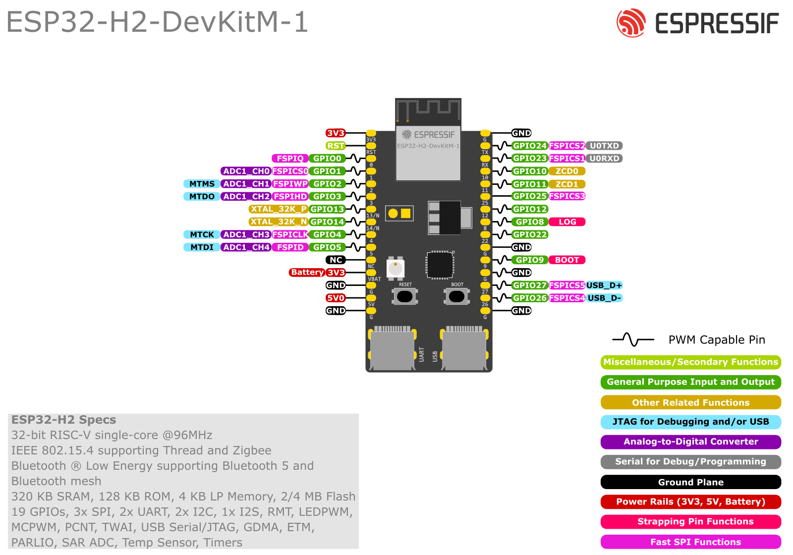
- usb — USB 2.0 Full-Speed (12 Mbps) USB-Serial/JTAG controller on GPIO26/27 (D−/D+) — device console + flashing + JTAG debug, not OTG (datasheet §1.2, §4.2.1.6; DevKitM-1 guide:
- On this board : 9 tutorials · 10 code
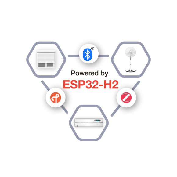
The ESP32-H2 represents a distinct strategic pivot in Espressif Systems’ product lineup, moving away from the ubiquitous Wi-Fi connectivity that defined earlier generations to focus exclusively on low-power, low-data-rate wireless standards. Introduced in 2021 with official development boards shipping in 2023, this system-on-chip is designed as a dedicated solution for Internet of Things applications that rely on IEEE 802.15.4 protocols, such as Zigbee and Thread, alongside Bluetooth 5 Low Energy. It is crucial to understand that the ESP32-H2 does not possess a Wi-Fi radio. This absence is not a defect but a deliberate design choice intended to reduce power consumption and silicon complexity for devices that do not require high-bandwidth internet access. Instead, the chip integrates a single 2.4 GHz radio that handles both 802.15.4 communications and Bluetooth LE, making it an ideal candidate for battery-operated mesh networks, smart home sensors, and Matter-over-Thread endpoints. While it lacks Wi-Fi, it is often paired with other Espressif chips, such as the ESP32-S3 or C6, which provide Wi-Fi connectivity and act as border routers, allowing the H2 to serve as a secure, low-power leaf node in a larger network.
At the heart of the ESP32-H2 is a single-core 32-bit RISC-V processor running at up to 96 MHz. For those unfamiliar with processor architectures, RISC-V is an open standard instruction set architecture, distinct from the ARM cores found in many other microcontrollers. This core operates on a four-stage pipeline, delivering approximately 303.38 CoreMark performance at its maximum frequency. The chip is manufactured using a 40 nm process, which balances cost and efficiency for embedded applications. Memory resources are tightly integrated, featuring 320 KB of SRAM for active data processing and 128 KB of ROM for boot code. A critical feature for power-sensitive applications is the 4 KB of Low-Power SRAM, which remains retained even when the chip is in deep-sleep mode, allowing the device to preserve state without drawing significant power. Storage is handled by in-package flash memory, available in 2 MB or 4 MB variants, with the ability to expand up to 16 MB using external SPI flash if needed. Notably, there is no PSRAM, reinforcing its role as a compact, efficient controller rather than a high-performance computing unit.
The connectivity capabilities of the ESP32-H2 are its defining characteristic. The integrated radio supports IEEE 802.15.4, which underpins the Zigbee and Thread protocols, offering a data rate of 250 Kbps using OQPSK modulation. It also supports Bluetooth 5 LE, including the Coded PHY feature which extends range at lower data rates of 125 and 500 Kbps. The radio is certified for Zigbee and Thread 1.3.0, ensuring interoperability with a vast ecosystem of smart home devices. Transmit power can be adjusted from -24 dBm to +20 dBm, with the higher power setting providing significant range for mesh networking nodes. Security is robust, featuring ECC-based secure boot, AES-128/256-XTS flash encryption, and hardware accelerators for ECDSA digital signatures and HMAC operations. This security suite is essential for devices that participate in secure mesh networks like Matter, where trust and data integrity are paramount.
Power efficiency is a major selling point for the ESP32-H2, particularly for battery-powered devices. In deep-sleep mode, the chip consumes a typical current of just 7 microamps, allowing coin-cell batteries to last for years in intermittent operation scenarios. Light-sleep mode draws between 25 and 85 microamps, while active receive mode consumes around 24 to 25 milliamps. Transmit current varies significantly with output power, ranging from 36 milliamps at 0 dBm to 140 milliamps at the maximum +20 dBm. To facilitate these low-power states, the chip includes a dedicated VBAT pin for battery domain power, separate from the main VDD3P3 supply. However, designers must be cautious with pin assignments, as GPIO12 is multiplexed with the VBAT and VDDA_PMU power pins, meaning it cannot be used as a general-purpose I/O if the battery domain is active. Furthermore, not all GPIOs are available during deep sleep; specifically, GPIO0 through GPIO5 and GPIO22 through GPIO27 are inactive in this state. Wake-up events must be triggered by pins in the Low-Power domain, such as GPIO6 through GPIO21, to ensure the chip can reliably exit sleep mode.
The ESP32-H2 features 19 programmable GPIOs, which is a relatively limited number compared to larger microcontrollers, requiring careful pin planning. The chip includes a USB 2.0 Full-Speed USB-Serial/JTAG controller on GPIO26 and GPIO27, providing a convenient single-port solution for programming, debugging, and serial console access without needing an external USB-to-UART bridge. This is a significant usability improvement, mirroring the design philosophy of the ESP32-C3. Peripherals include two UARTs, one general-purpose SPI interface, two I2C interfaces, one I2S interface, and a TWAI controller compatible with CAN 2.0A, making it suitable for industrial applications as well as consumer electronics. An analog-to-digital converter with 12-bit resolution and up to five channels is available, along with a temperature sensor and analog comparator, though there is no digital-to-analog converter.
Software support for the ESP32-H2 is mature, with official support in ESP-IDF since version 5.1. Developers can use the ESP-Zigbee-SDK and ESP-Matter frameworks to build compliant devices. Arduino support is also available through the espressif/arduino-esp32 core, although users should note that the official PlatformIO platform does not yet fully support the H2, requiring the use of community forks like pioarduino. A common pitfall for developers porting code from Wi-Fi-enabled ESP32 variants is the complete absence of Wi-Fi libraries; any code attempting to initialize Wi-Fi will fail. Additionally, on the official DevKitM-1 board, GPIO8 is used for an addressable RGB LED but is also a strapping pin, which can cause boot issues if not handled correctly. Early revisions of the DevKitM-1 also lacked a 32.768 kHz crystal, affecting real-time clock accuracy. Despite these considerations, the ESP32-H2 stands as a powerful, certified, and energy-efficient solution for the next generation of low-power wireless IoT devices.
Pinout diagram
| Attr | Specs | verified |
|---|---|---|
cpu | single-core 32-bit ESP-RISC-V, four-stage pipeline, up to 96 MHz; 303.38 CoreMark at 96 MHz (3.16 CoreMark/MHz); 40 nm process (datasheet §4.1.1.1: process node: | ✔ |
gpu | none (embedded MCU). | ? unverified |
memory | 320 KB SRAM, 128 KB ROM, 4 KB LP SRAM (retained in deep-sleep), 16 KB cache (product page + datasheet §4.1.2). | ? unverified |
storage | 2 MB or 4 MB SiP in-package flash; SPI/Dual/Quad/QPI interface supports up to 16 MB off-package flash (datasheet §1.2, §4.1.2.2). No PSRAM. | ? unverified |
connectivity | one 2.4 GHz radio combining IEEE 802.15.4 (Thread, Zigbee, Matter over Thread; 250 Kbps OQPSK PHY, RX sensitivity up to −102.5 dBm) and Bluetooth 5 (LE) incl. Coded PHY/Long Range 125 & 500 Kbps (RX sensitivity up to −106.5 dBm) and Bluetooth Mesh; TX power −24 to +20 dBm (datasheet §1.2/§5; product page). No Wi-Fi, no Bluetooth Classic — that is the key difference vs ESP32-C6, which adds Wi-Fi 6 ( | ✔ |
usb | USB 2.0 Full-Speed (12 Mbps) USB-Serial/JTAG controller on GPIO26/27 (D−/D+) — device console + flashing + JTAG debug, not OTG (datasheet §1.2, §4.2.1.6; DevKitM-1 guide: | ✔ |
gpio | 19 programmable GPIOs; digital pins GPIO0–GPIO5 and GPIO22–GPIO27 are NOT usable in deep-sleep (LP-domain pins only); GPIO26/27 default to USB function with internal pull-up; default drive strength 20 mA (40 mA on GPIO26/27) (datasheet §2.2–2.3). - Peripherals: 2× UART, 1× general-purpose SPI (plus 2 dedicated flash SPI ports), 2× I2C, 1× I2S, RMT (2 TX + 2 RX channels), LED PWM (6 channels), TWAI (CAN 2.0A), GDMA (3 TX + 3 RX channels), SoC event task matrix (ETM) (datasheet §1.2). - ADC: 12-bit SAR, up to 5 channels; plus temperature sensor and analog (PAD voltage) comparator; no DAC in the datasheet peripheral set (datasheet §1.2, §4.2.2). | ? unverified |
logic_level | 3.3 v | ? unverified |
power | VDD3P3 (3.0–3.6 V abs-max 3.6 V) + VBAT pin (battery domain, shared with GPIO12/XTAL_32K functions); CHIP_EN must not float (datasheet §2.5, §5.1). | ? unverified |
consumption_3_3_v_25_c_datasheet_table_5_6_5_9 | TX 36 mA @ 0 dBm / 140 mA @ +20 dBm; RX 24–25 mA; modem-sleep 3–17 mA typ; light-sleep 25–85 µA typ; deep-sleep 7 µA typ; power-off 1 µA. | ? unverified |
temperature | −40 to +105 °C recommended ambient (FH-S parts); HTOL qualified 125 °C/1000 h (datasheet Table 1-1, §5.6). | ? unverified |
- Manufacturer: Espressif Systems (Shanghai) — product page:
- Year: introduced 2021; first official development board (DevKitM-1) shipped 2023 ( ESP-IDF support landed in v5.1 (
- Status: Active — Espressif's dedicated low-power 802.15.4 (Thread/Zigbee) + Bluetooth 5 (LE) SoC; the "H" line has no Wi-Fi radio (product page above; the H2 page lists only IEEE 802.15.4 + Bluetooth LE as radios).
- Launch price: DevKitM-1 ≈ US$10 at retail (2023, shipping excluded); Waveshare ESP32-H2-DEV-KIT-N4-M ≈ US$6.65: ESP32-H2FH2S (2 MB in-package Quad SPI flash) and ESP32-H2FH4S (4 MB), both rated −40 to +105 °C ambient, 3.3 V SPI (ESP32-H2 Series Datasheet v1.3, Table 1-1: Nomenclature: H = high-temperature grade, N = normal grade, S = security-enhanced (datasheet Fig. 1-1).
- Modules: ESP32-H2-MINI-1 (PCB antenna) / ESP32-H2-MINI-1U (external antenna connector) (
- Common boards: ESP32-H2-DevKitM-1 / -1U-N4 (official), Waveshare ESP32-H2-DEV-KIT-N4-M and ESP32-H2-Zero, Olimex ESP32-H2-DevKit-LiPo, LILYGO T-Panel (S3 + H2 gateway), M5Stack Unit Gateway H2 and NanoH2 (
+ Strengths
- Zigbee-Compliant Platform and Thread-Certified 1.3.0 Component — certified, not just "capable" (badges/links on product page:
- Matter-over-Thread endpoint with concurrent 802.15.4 + BLE commissioning; combined with a Wi-Fi SoC it forms a Thread border router or Matter-Zigbee bridge (product page; e.g. LILYGO T-Panel S3+H2 gateway:
- 7 µA deep-sleep with 4 KB LP SRAM retention — battery mesh nodes (datasheet Table 5-9).
- +20 dBm (100 mW) TX option on a sub-$3-class mesh radio (datasheet §5.5.1).
- Security: ECC-based secure boot, AES-128/256-XTS flash encryption, ECDSA digital signature, HMAC peripheral, crypto accelerators (product page "Robust Security").
- USB-Serial/JTAG built in — one port for console/flash/debug, like the C3 lineage.
- Spiritual successor to the ESP32-C3 for home automation: same RISC-V + USB-Serial/JTAG + security recipe, but the Wi-Fi radio is traded for 802.15.4, making it Espressif's answer to Thread/Zigbee deployments (interpretation from the two product pages: vs
− Weaknesses
- No Wi-Fi. Anything copied from ESP32/C3/C6 examples that touches Wi-Fi or Matter-over-Wi-Fi simply cannot run; a Thread border router must pair the H2 with a Wi-Fi SoC (product page "Enabling Matter"). This is the #1 porting surprise.
- GPIO8 is a strapping pin AND the DevKitM-1's RGB LED line (addressable RGB LED on GPIO8): loading GPIO8 at reset (LED capacitance, driving it as an input with a pull) can drop the chip into the wrong boot mode (strapping pins GPIO8/9/25: datasheet §3; RGB LED: DevKitM-1 user guide URL above).
- Deep-sleep wake-up pin restriction: GPIO0–5 and GPIO22–27 are dead in deep-sleep — buttons/sensors that must wake the chip must sit on LP-domain pins (datasheet §2.2).
- GPIO12 is multiplexed with the VBAT/VDDA_PMU power pins — battery-powered designs that also want GPIO12 as IO must resolve the power scheme first (datasheet Table 2-7).
- ADC accuracy depends on manufacturing date code: Espressif documents different ADC range/accuracy for chips before vs after D/C 342023 (shielded parts) — mixed batches can behave differently (datasheet note under §5.4).
- Early DevKitM-1 boards (PW before PW-2024-02-0362, i.e. pre-Feb-2024) ship without the 32.768 kHz LP crystal — worse RTC accuracy and higher average sleep power unless you populate one (DevKitM-1 user guide, Hardware Revision Details).
- CHIP_EN must never float (chip may stay off or brown-out unpredictably) (datasheet Table 2-6 note).
- Official PlatformIO platform lacks H2 — PlatformIO users must switch to the pioarduino fork (
- Only 19 GPIOs / 2 UARTs / 1 general SPI port, and on SiP-flash QFN32 parts the flash SPI pins are not routed out (datasheet Table 1-1 note 2). Pin planning is mandatory.
- >
- Retour d'expérience expert expert — expert-microcontroleur
- Je viens de passer mes premiers jours sur l'ESP32-H2 et le retour est mitigé. Le point positif majeur reste son efficience : la 303.38 CoreMark à 96 MHz sur le RISC-V est impressionnante pour le budget, et la connectivité 802.15.4 est native. Par contre, attention aux pièges de portage. Si vous cop… — expert-microcontroleur
- Merci pour ce retour précis, ça confirme mes doutes. J'ai justement perdu trois heures ce matin à chercher pourquoi mon code ne bootait pas, avant de comprendre que mon bouton de reset était mal branché près du GPIO8. C'est vraiment vicieux cette multiplexage avec la LED. En tout cas, merci de conf… — hacker-du-weekend
- Salut, petite question pratique concernant l'environnement de dev. J'utilise PlatformIO au quotidien pour mes projets ESP32, mais je ne trouve pas de support natif pour cette puce. Tu as réussi à faire tourner un blink simple ? J'ai lu quelque part qu'il fallait changer de plateforme, mais je ne ve… — pio_addict
Community feedback and projects
- Use Arduino IDE and ESP32-H2-DEVKITM-1 to create a Matter device forum.arduino.cc
- Using ESP32 H2 Super Mini forum.arduino.cc
- How to correctly power an ESP32-H2 board with a battery electronics.stackexchange.com
- ESP32-H2 doesn't work fine when powered via external supply and 3V3 pin electronics.stackexchange.com
- No Wi-Fi. Anything copied from ESP32/C3/C6 examples that touches Wi-Fi or Matter-over-Wi-Fi simply cannot run; a Thread border router must pair the H2 with a Wi-Fi SoC (product page "Enabling Matter"). This is the #1 porting surprise.
- GPIO8 is a strapping pin AND the DevKitM-1's RGB LED line (addressable RGB LED on GPIO8): loading GPIO8 at reset (LED capacitance, driving it as an input with a pull) can drop the chip into the wrong boot mode (strapping pins GPIO8/9/25: datasheet §3; RGB LED: DevKitM-1 user guide URL above).
- Deep-sleep wake-up pin restriction: GPIO0–5 and GPIO22–27 are dead in deep-sleep — buttons/sensors that must wake the chip must sit on LP-domain pins (datasheet §2.2).
- GPIO12 is multiplexed with the VBAT/VDDA_PMU power pins — battery-powered designs that also want GPIO12 as IO must resolve the power scheme first (datasheet Table 2-7).
- ADC accuracy depends on manufacturing date code: Espressif documents different ADC range/accuracy for chips before vs after D/C 342023 (shielded parts) — mixed batches can behave differently (datasheet note under §5.4).
- Early DevKitM-1 boards (PW before PW-2024-02-0362, i.e. pre-Feb-2024) ship without the 32.768 kHz LP crystal — worse RTC accuracy and higher average sleep power unless you populate one (DevKitM-1 user guide, Hardware Revision Details).
- CHIP_EN must never float (chip may stay off or brown-out unpredictably) (datasheet Table 2-6 note).
- Official PlatformIO platform lacks H2 — PlatformIO users must switch to the pioarduino fork (
- Only 19 GPIOs / 2 UARTs / 1 general SPI port, and on SiP-flash QFN32 parts the flash SPI pins are not routed out (datasheet Table 1-1 note 2). Pin planning is mandatory.
- >
- Premier blink sur une broche sûre (GPIO22) debutant Schéma : IMG-esp32-h2-debutant-1-h2-clignoter-gpio22.svg — ESP32-H2-DevKitM-1 avec une LED externe et sa résistance sur GPIO22, broches déconseillées GPIO8 (strapping + LED RGB) et GPIO26/27 (USB) barrées.
- Pilotez la LED RGB embarquée avec le périphérique RMT debutant Schéma : IMG-esp32-h2-debutant-2-h2-led-rgb-rmt-gpio8.svg — Bloc RMT du H2 générant la trame WS2812 envoyée sur GPIO8 vers la LED RGB adressable du DevKitM-1, avec badge strapping sur GPIO8.
- Beacon BLE 5 : le « hello radio » d'une puce sans Wi-Fi debutant Schéma : IMG-esp32-h2-debutant-3-h2-beacon-ble5-nimble.svg — H2 diffusant des trames d'advertising BLE 5 captées par un téléphone, avec badges Coded PHY 125/500 kbps et TX jusqu'à +20 dBm.
- Deep-sleep 7 µA : le bouton qui doit être dans le domaine LP intermediaire Schéma : IMG-esp32-h2-intermediaire-1-h2-deep-sleep-bouton-lp.svg — Broches du H2 colorées : GPIO0–5 et GPIO22–27 grisées (mortes en deep-sleep), bouton de réveil sur GPIO6 dans le domaine LP, puce en deep-sleep à 7 µA sur batterie.
- Interrupteur Zigbee certifié avec l'ESP-Zigbee-SDK intermediaire Schéma : IMG-esp32-h2-intermediaire-2-h2-zigbee-light-switch.svg — Interrupteur Zigbee H2 sur pile avec bouton en domaine LP, rejoignant un coordinateur relié à un réseau IP.
- ADC 12 bits et capteur de température : piège du date code intermediaire Schéma : IMG-esp32-h2-intermediaire-3-h2-adc-capteur-interne.svg — Blocs analogiques du H2 : ADC SAR 12 bits 5 canaux, capteur de température et comparateur analogique, sans DAC, reliés à la console USB-Serial/JTAG.
- Endpoint Matter-over-Thread sur esp-matter avance Schéma : IMG-esp32-h2-avance-1-h2-matter-over-thread.svg — Endpoint Matter H2 commissionné en BLE puis rattaché à un réseau Thread dont la sortie IP passe par un border router S3/C6.
- Passerelle domotique : le duo Wi-Fi + H2 avance Schéma : IMG-esp32-h2-avance-2-h2-passerelle-wifi-dual-soc.svg — Architecture de passerelle : un SoC Wi-Fi (S3 ou C6) relié à un H2 pour le radio 802.15.4, le tout remontant les événements vers un broker IP.
- Nœud de capteur maillé sur pile : le système complet avance Schéma : IMG-esp32-h2-avance-3-h2-noeud-mesh-batterie.svg — Cycle de vie d'un nœud sur pile : réveil LP, lecture ADC/capteur, burst radio 802.15.4 ou BLE, retour deep-sleep 7 µA, avec broche GPIO12/VBAT annotée.
Code library — examples written for this board
blink_main.cCbouton_isr.cCledc_fade.cCadc_oneshot.cCuart_console.cCi2c_oled.cCzigbee_switch.cCmatter_switch.cppC++deep_sleep.cCnvs_store.cC
Examples and repos found online
- espressif/esp-idf github.com
- espressif/esp-zigbee-sdk github.com
- barsik21/esp32h2-thermo github.com