M5Stack Encoder Motor Driver Unit (DRV8837DSGR)
⚡ The essentials in 60 seconds
- MCU — STM32G031G8U6
- Motor Driver — DRV8837DSGR H-bridge
- Communication — I2C (Default address 0x2F, configurable 0x08-0x77)
- Channels — Single-channel encoder motor drive
- Encoder Support — Single-channel AB encoder, 3 ~ 15 PPR
- Motor Interface — PH2.0-6P (M+ / M- / GND / 5V / EN_B / EN_A)
- On this board : 9 tutorials · 10 code
Imagine a small, unassuming module that fits comfortably in the palm of your hand, yet possesses the intelligence to control a motor with the precision of a seasoned engineer. This is the Encoder Motor Driver Unit, a compact device designed to bridge the gap between simple motor spinning and sophisticated, feedback-driven motion control. At its heart lies a microcontroller, specifically the STM32G031G8U6, which acts as the brain of the operation. This chip is not merely a passive switch; it is an active processor capable of making thousands of calculations per second to ensure that a motor moves exactly as you command. The unit is built around the DRV8837DSGR, a specialized integrated circuit known as an H-bridge. To understand what an H-bridge does, think of it as a set of electronic gates that can reverse the direction of electrical current flowing through a motor. By flipping these gates, the driver can make the motor spin forward or backward, a fundamental requirement for any robotic arm, wheeled robot, or automated mechanism that needs to move in two directions.
The physical footprint of this unit is remarkably small, measuring just 32.1 millimeters in length, 24.0 millimeters in width, and 8.0 millimeters in height, with a weight of only 4.8 grams. This diminutive size makes it ideal for projects where space is at a premium, such as wearable technology or miniature robots. Despite its small stature, it is a single-channel driver, meaning it is designed to control one motor at a time. This focus allows it to dedicate all its resources to managing that single motor with high fidelity. It is particularly well-suited for two common types of hobbyist motors: the six-wire geared motors, which come with built-in encoders, and the ubiquitous TT motors often found in basic robotics kits. The connection to the motor is handled via a PH2.0-6P connector, which provides the necessary pathways for power and signal, including the motor positive and negative terminals, ground, a five-volt supply, and the encoder channels labeled EN_A and EN_B.
What truly sets this unit apart from basic motor drivers is its ability to handle feedback. The term "encoder" refers to a sensor attached to the motor shaft that counts how many times the shaft has turned. This unit supports AB encoders with a resolution ranging from 3 to 15 pulses per revolution. While this might sound like a small number, it provides the essential data needed for closed-loop control. In an open-loop system, you tell a motor to spin for a certain amount of time, hoping it moves the correct distance. In a closed-loop system, the microcontroller constantly compares the desired position or speed with the actual position or speed reported by the encoder. If the motor is lagging behind, the driver increases the power; if it is moving too fast, the driver reduces it. This results in precise speed control and accurate positioning, which is critical for tasks like drawing precise shapes or maintaining a steady speed on an uneven surface.
The unit offers several modes of operation to suit different needs. For simple applications, you can use Pulse Width Modulation, or PWM, to control the average voltage sent to the motor, thereby adjusting its speed. You can also command it to move forward or reverse. For more advanced applications, the closed-loop modes take over, allowing you to specify a target speed or a specific angle for the motor to reach. Additionally, there are soft start and soft stop features. These functions gradually ramp the power up or down, preventing sudden jerks that could damage gears or cause a robot to tip over. This smooth acceleration and deceleration are handled internally by the microcontroller, sparing the user from writing complex timing code.
Communication with this unit is handled via the I2C protocol, a standard method for devices to talk to each other in electronics projects. By default, the unit listens at the address 0x2F, but this can be configured to any address between 0x08 and 0x77, allowing multiple units to coexist on the same communication bus without conflict. This digital interface means that you send commands and receive data in a structured format, making it easy to integrate into larger systems controlled by platforms like Arduino, Raspberry Pi, or ESP32. The Grove interface compatibility further simplifies wiring, as it uses standardized connectors that prevent accidental misconnections, a common frustration for beginners.
Power management is another critical aspect of this module. It accepts an external DC power supply ranging from 6 to 12 volts via a two-pin connector. This external power is crucial because motors can draw significant current, which might overwhelm the logic circuits if they were powered directly from the main controller. The unit internally converts this higher voltage down to a stable 5 volts to power the motor and the Grove interface. The maximum load it can handle is 1.2 amperes at 5 volts when using the external supply. This specification ensures that the motor has enough "muscle" to perform work while keeping the electronics safe. To monitor this power usage, the unit integrates an INA199A current detection circuit. This component acts like a sensor for electricity, measuring how much current the motor is drawing in real-time. This information can be read by the microcontroller and reported back to the main system, allowing for advanced features like stall detection or power consumption logging.
Finally, the unit includes a small but useful visual indicator: a programmable RGB LED, specifically a WS2812C-2020 model. This single light can display any color in the spectrum, providing immediate visual feedback about the state of the driver. It could be programmed to glow green when the motor is running correctly, red when an error is detected, or blue when the system is idle. This simple feature enhances the user experience by making the internal state of the device visible without needing to connect a computer or display screen. Priced at an indicative 9.50 USD, this module represents a significant value proposition, offering professional-grade control features in a package that is accessible to hobbyists, students, and educators alike. It transforms the complex task of motor control into a manageable, plug-and-play experience, allowing creators to focus on the bigger picture of their projects rather than getting bogged down in the low-level details of electrical engineering.
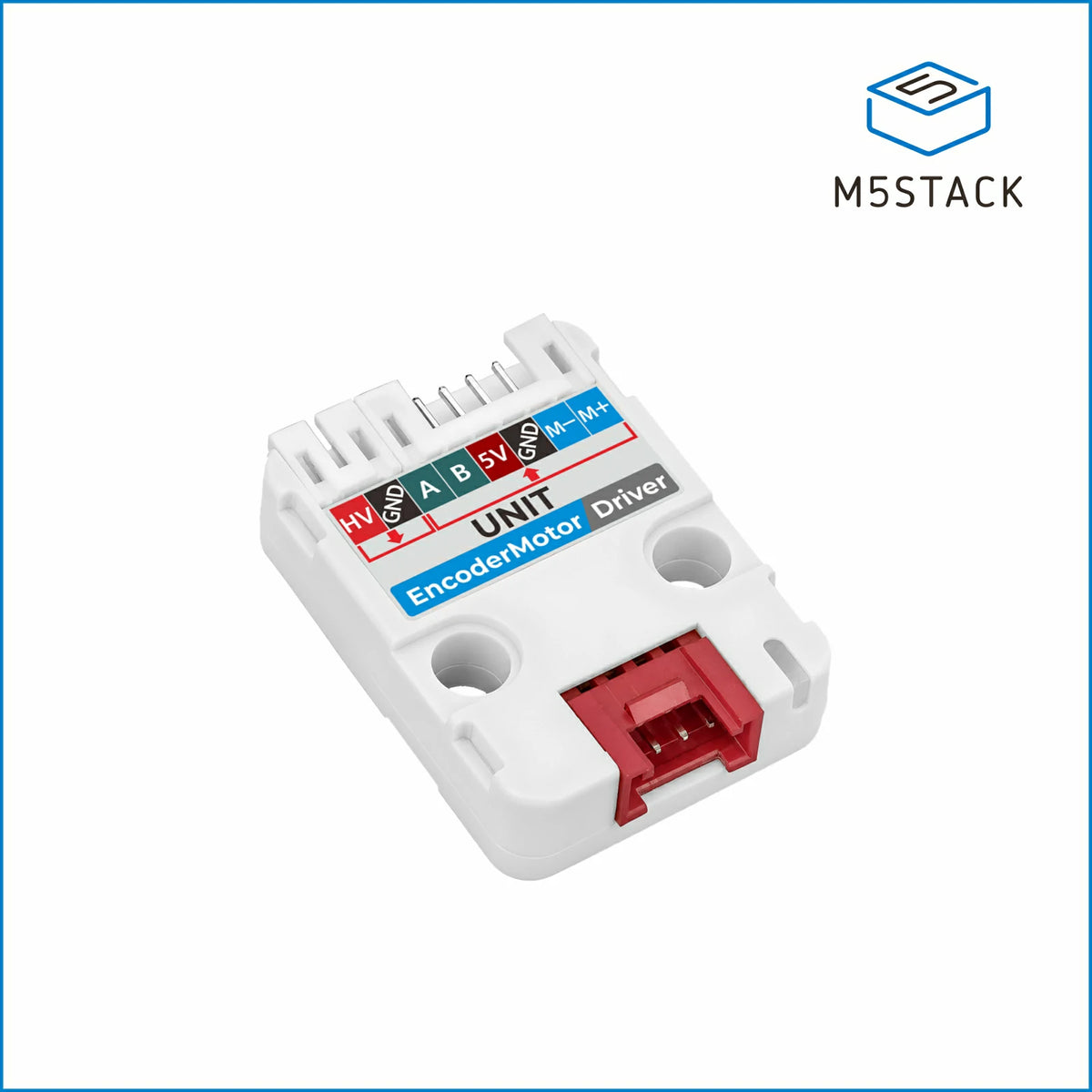
| Attr | Specs | verified |
|---|---|---|
MCU | STM32G031G8U6 | ? unverified |
Motor Driver | DRV8837DSGR H-bridge | ? unverified |
Communication | I2C (Default address 0x2F, configurable 0x08-0x77) | ? unverified |
Channels | Single-channel encoder motor drive | ? unverified |
Encoder Support | Single-channel AB encoder, 3 ~ 15 PPR | ? unverified |
Motor Interface | PH2.0-6P (M+ / M- / GND / 5V / EN_B / EN_A) | ? unverified |
Power Input | External DC 6 ~ 12V (PH2.0-2P) or Grove DC 5V | ? unverified |
Motor Load | Max DC 5V @ 1.2A (external supply) | ? unverified |
Current Detection | INA199A circuit | ? unverified |
LED | 1x Programmable RGB (WS2812C-2020) | ? unverified |
Dimensions | 32.1 x 24.0 x 8.0 mm | ? unverified |
Weight | 4.8 g | ? unverified |
Control Modes | PWM speed, Forward/Reverse, Speed/Position closed-loop, Soft start/stop | ? unverified |
This Grove unit from M5Stack is designed for precise DC motor control using a DRV8837DSGR H-bridge. It relies on an STM32G031G8U6 microcontroller to handle I2C communication and closed-loop algorithms.
+ Strengths
["- Closed-loop speed and position control with AB encoder support (3-15 PPR).","- Integrated INA199A current sensing circuit and programmable WS2812C RGB LED.","- Compatible with 6-wire gear motors and TT motors via PH2.0-6P interface."]
− Weaknesses
["- Single-channel design limited to one motor per unit.","- Maximum load restricted to 1.2A at 5V.","- Requires external DC 6-12V power supply for optimal performance."]
- Retour d'expérience expert expert — expert-microdb
- Après deux semaines d'utilisation sur mon robot, je confirme que l'Encoder Motor Driver Unit (DRV8837DSGR) de M5Stack est bluffante pour sa taille (32x24mm). Le STM32G031 et le pont DRV8837 gèrent bien la boucle fermée position/vitesse. Attention : l'adresse I2C est 0x2F par défaut. Le courant max … — expert-microdb
- Merci pour le feedback. Je galère avec les encodeurs AB de 15 PPR, le signal semble bruité. Tu utilises le mode démarrage progressif ? J'ai aussi remarqué que la conversion 6-12V en 5V chauffe légèrement sous charge max. L'INA199A aide à surveiller ça. Quelqu'un a testé avec l'adresse 0x08 sans con… — membre-forum
Community feedback and projects
Content not available yet.
Content not available yet.
Content not available yet.
["- not specified"]
- First connection and startup of the Encoder Motor Driver Unit debutant Apprenez à connecter physiquement l'unité DRV8837DSGR et à vérifier sa communication I2C de base.
- Mastering I/O with the Encoder Motor Driver Unit debutant Apprenez à utiliser la LED RGB intégrée et à lire les données de l'encodeur via I2C pour un contrôle visuel et positionnel basique.
- Automating Precise Movement with the Encoder Motor Driver debutant Apprenez à configurer un mouvement en boucle fermée pour un positionnement précis et répétable.
- First Setup of the Encoder Motor Driver intermediaire Apprenez à brancher, alimenter et initialiser l'unité DRV8837DSGR pour un premier test fonctionnel.
- GPIO and RGB LED Control on the Encoder Motor Driver Unit intermediaire Apprenez à utiliser les extensions GPIO de l'unité pour piloter des périphériques externes tout en gérant le moteur.
- Encoder feedback automation with DRV8837 intermediaire Mettez en place une boucle de régulation PID pour maintenir une position précise en temps réel.
- Advanced Configuration and I2C Bus Validation avance Apprenez à configurer l'adresse I2C personnalisée et à valider la communication avec le DRV8837DSGR via le registre de statut.
- Controlling GPIOs and Peripherals on the Encoder Motor Driver Unit avance Exploitez les capacités avancées de l'Encoder Motor Driver Unit pour gérer les entrées-sorties, la LED RGB et l'affichage via son microcontrôleur STM32.
- Distributed Automation: Precise Control and Telemetry with the Encoder Motor Driver Unit avance Intégrez l'unité DRV8837DSGR dans un système IoT pour un contrôle en boucle fermée synchronisé et une remontée de données en temps réel.
Code library — examples written for this board
m5stack-encoder-motor-i2c-esp32.inoC++ (Arduino)m5stack-encoder-motor-pwm-control.inoC++ (Arduino)m5stack-encoder-motor-closed-loop.inoC++ (Arduino)m5stack-encoder-motor-position-control.inoC++ (Arduino)m5stack-encoder-motor-led-status.inoC++ (Arduino)closed_loop_speed_pid.pyMicroPythonposition_control_absolute.pyMicroPythonrgb_status_indicator.pyMicroPythoncurrent_monitoring_safety.pyMicroPythonsoft_start_stop_profile.pyMicroPython