Raspberry Pi Compute Module 3+ (CM3+ / CM3+ Lite)
⚡ The essentials in 60 seconds
- soc — Broadcom BCM2837B0 — the revised silicon of the Raspberry Pi 3 Model B+ (same part as the Pi 3B+), quad-core Arm Cortex-A53 (ARMv8-A), capped at 1.2 GHz on the module (datasheet §1 and §10 "maximum working frequency of 1.2 GHz"; CNX launch article notes the B0 die can reach 1.4 GHz on the 3B+ board but is limited to 1.2 GHz here by the module power supply).
- gpu — Broadcom VideoCore IV (docs model table, introduction.adoc).
- ram — 1 GB LPDDR2 (the only option; datasheet §1).
- storage — on-module eMMC 8/16/32/64 GB on non-Lite variants; eMMC I/O voltage is fixed at 1.8 V and the eMMC signals are NOT accessible on module pins. CM3+ Lite exposes SDX_CLK/CMD/D0–D3 + SDX_VDD (1.8–3.3 V) instead (datasheet §1, §3 block diagram, §5 pin table).
- connectivity — No Wi-Fi, no Bluetooth, no Ethernet, no PCIe on the module. Full peripheral list on the 200-pin edge connector: 48× GPIO, 2× I2C, 2× SPI, 2× UART, 2× SD/SDIO, 1× HDMI 1.3a, 1× USB 2.0 host/OTG, 1× DPI (24-bit parallel RGB), 1× SMI (NAND/Intel-mode-80 bus), 4-lane + 2-lane MIPI CSI (up to 1 Gbps/lane each), 4-lane + 2-lane MIPI DSI, composite TV-out (TVDAC), JTAG/Debug (VC_TCK/TMS/TDI/TDO/TRST_N) (datasheet §2.2, §5, §9).
- gpio — 48 usable lines in two independently powered banks — bank0 GPIO0–27 (GPIO0-27_VDD) and bank1 GPIO28–45 (GPIO28-45_VDD); each bank rail sets that bank's I/O level anywhere from 1.8 V to 3.3 V and must be powered even if unused. Weak internal pulls 50–65 kΩ on all but GPIO28/29/44/45 (no default pull — add off-chip pulls); default drive 8 mA, max 16 mA/pin, ≤50 mA aggregate per bank. Alternate functions include PWM0/1, GPCLK0–2, PCM (I2S), SPI1/2, UART1/2 (datasheet §6 tables, §9.1, Tables 7–8). No ADC and no DAC on the SoC (only the composite video DAC).
- On this board : 9 tutorials · 10 code
The Raspberry Pi Compute Module 3+ represents a specialized evolution of the single-board computer philosophy, designed not for hobbyists plugging in a keyboard and monitor, but for engineers and manufacturers embedding computing power into custom hardware. Launched in January 2019, this module is part of the Compute Module family, which strips away the bulky connectors and standard ports of a typical Raspberry Pi to offer a compact, solderable or socketed component. The CM3+ comes in two primary forms: the standard CM3+, which includes onboard eMMC storage ranging from 8 to 64 gigabytes, and the CM3+ Lite, which omits this storage entirely to save cost and allow designers to attach their own SD card or flash memory. Both variants share the same core architecture, making them drop-in replacements for the earlier Compute Module 3, while offering significant internal upgrades. The module is currently supported with a guaranteed availability until at least January 2028, ensuring long-term stability for industrial projects that require extended lifecycle support.
At the heart of the CM3+ lies the Broadcom BCM2837B0 system-on-chip, the same silicon found in the Raspberry Pi 3 Model B+. This chip features a quad-core Arm Cortex-A53 processor, which is a 64-bit capable architecture based on the ARMv8-A instruction set. While the processor is technically capable of running at higher speeds, the module caps its clock frequency at 1.2 GHz. This limitation is not a defect but a deliberate design choice to manage power consumption and heat dissipation within the compact form factor of the module. The system includes 1 GB of LPDDR2 RAM, which is soldered directly onto the module, providing sufficient memory for most embedded applications. For graphics, it utilizes the Broadcom VideoCore IV GPU, capable of handling basic display outputs and video decoding. Unlike the standard Raspberry Pi boards, the CM3+ does not include Wi-Fi, Bluetooth, or Ethernet on the module itself. This absence is intentional, allowing designers to choose their own connectivity solutions via the exposed interfaces, keeping the module versatile for various industrial needs.
The physical interface of the CM3+ is its most distinctive feature. It utilizes a 200-pin DDR2-SODIMM form factor, which is mechanically compatible with standard laptop memory slots. This means the module can be plugged into a carrier board using a standard socket, simplifying assembly and allowing for easy replacement or upgrading of the compute unit without soldering. However, it is crucial to note that while it fits mechanically, it is not electrically compatible with standard DDR2 memory; it requires a custom carrier board designed specifically for Raspberry Pi Compute Modules. The edge connector exposes a vast array of input and output options, including 48 general-purpose input/output lines. These GPIOs are divided into two independent banks, each with its own power supply rail. This allows designers to set the voltage level of each bank independently between 1.8 volts and 3.3 volts, facilitating communication with a wide variety of sensors and peripherals that may operate at different voltage standards. The module also provides multiple communication interfaces, such as two I2C, two SPI, and two UART ports, along with HDMI 1.3a for video output, a single USB 2.0 port for host or device mode, and MIPI interfaces for cameras and displays.
One of the critical considerations when working with the CM3+ is its power management and boot process. The module requires six distinct power supplies to operate correctly, including specific rails for the core processor, memory, and the GPIO banks. These supplies must be powered in a specific sequence, typically highest voltage first or simultaneously, to prevent electrical latch-up, a condition where the chip becomes stuck in an invalid state. The boot process is also unique compared to standard Raspberry Pi boards. The CM3+ does not have a bootloader EEPROM, which is a small chip that stores boot configuration data on newer models. Instead, it relies on a fixed silicon boot order. When powered on, it first attempts to boot from the onboard eMMC or an SD card if present. If that fails, it falls back to waiting for boot code over USB. This USB boot capability is essential for manufacturing and development, as it allows the module to be flashed with an operating system from a host computer using a tool called rpiboot. However, forcing USB boot requires specific hardware manipulation, such as shorting a pin to ground, which introduces a slight delay during startup.
Software compatibility is another vital aspect. The CM3+ runs the same operating systems as the Raspberry Pi 3 Model B+, primarily the 32-bit version of Raspberry Pi OS. Because the processor supports 64-bit instructions, 64-bit operating systems can also be used, although the default and most stable configuration remains 32-bit. A significant caveat for users upgrading from older Compute Module 3 units is the firmware requirement. The CM3+ requires a software image dated November 2018 or newer to boot correctly. Older images created for the CM3 will not work, acting as a common pitfall for those reusing old storage media. The module’s thermal characteristics also demand attention; while it can operate in temperatures ranging from -25°C to +80°C, the processor will throttle its speed if the internal temperature exceeds 80°C to prevent damage. This thermal management is crucial in sealed enclosures where airflow is limited, requiring careful thermal design in the final product.
Despite its strengths, the CM3+ has limitations that designers must acknowledge. It lacks modern connectivity features like PCIe, which are available on newer Compute Module 4 and 5 models. The single USB 2.0 bus can become a bottleneck for applications requiring high-speed data transfer or multiple peripherals. Additionally, the MIPI camera and display interfaces are restricted to a limited set of officially supported sensors and displays, making third-party hardware integration more challenging. As the industry moves forward, new designs are often steered toward the Compute Module 4S or CM5, which offer more performance and features. However, for existing projects or those requiring the specific pinout and form factor of the CM3, it remains a robust, supported, and cost-effective solution. Its longevity commitment until 2028 ensures that developers can continue to rely on it for products with long deployment cycles, provided they plan for eventual migration to newer architectures. The CM3+ stands as a bridge between the early days of embedded Linux and the modern era of modular computing, offering a balance of performance, flexibility, and industrial reliability.

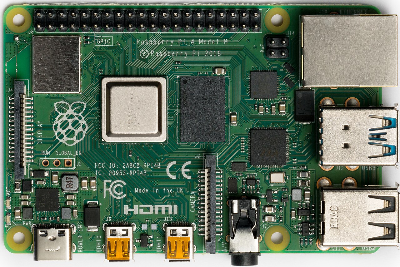
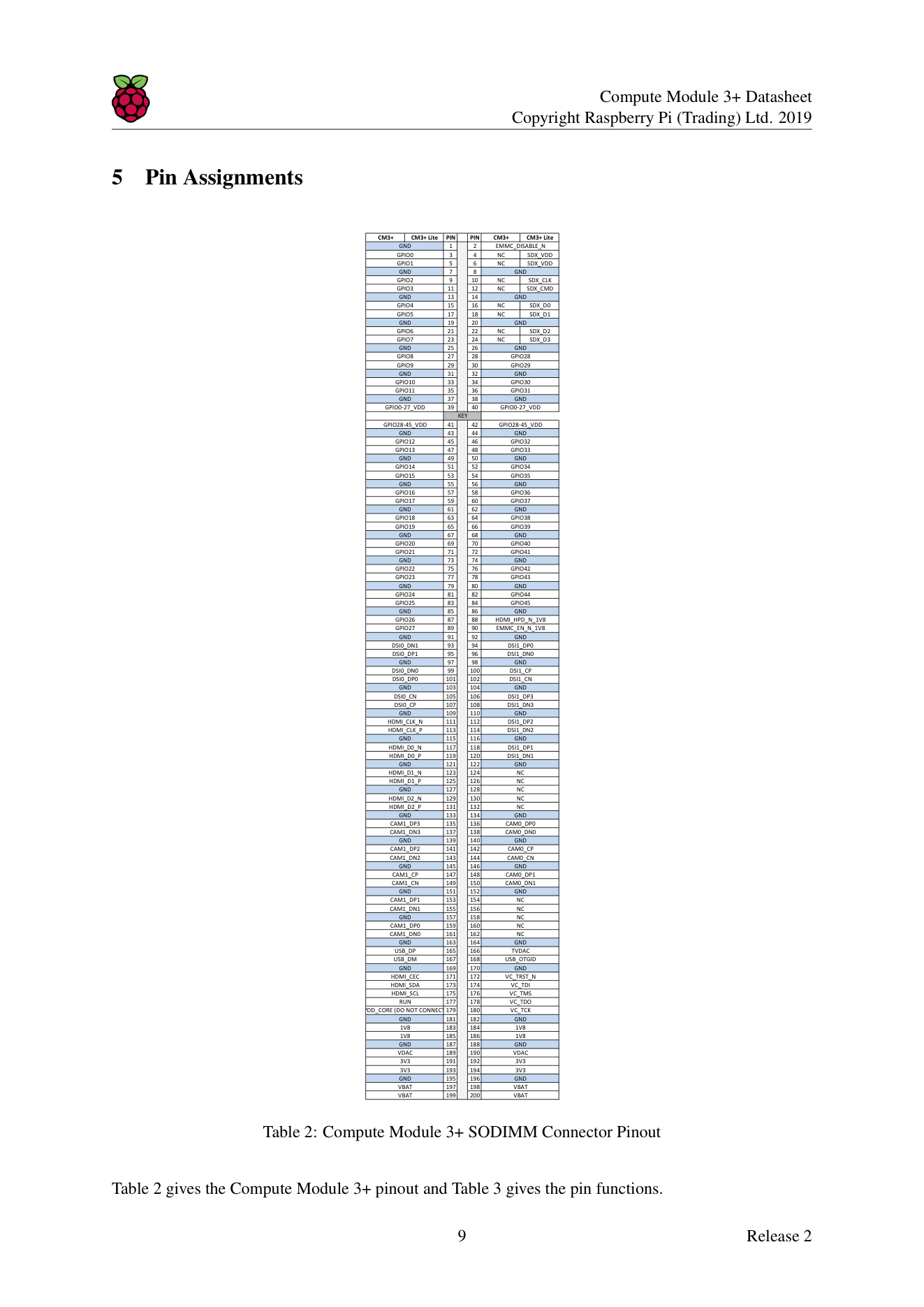
Pinout diagram
| Attr | Specs | verified |
|---|---|---|
soc | Broadcom BCM2837B0 — the revised silicon of the Raspberry Pi 3 Model B+ (same part as the Pi 3B+), quad-core Arm Cortex-A53 (ARMv8-A), capped at 1.2 GHz on the module (datasheet §1 and §10 "maximum working frequency of 1.2 GHz"; CNX launch article notes the B0 die can reach 1.4 GHz on the 3B+ board but is limited to 1.2 GHz here by the module power supply). | ? unverified |
gpu | Broadcom VideoCore IV (docs model table, introduction.adoc). | ? unverified |
ram | 1 GB LPDDR2 (the only option; datasheet §1). | ? unverified |
storage | on-module eMMC 8/16/32/64 GB on non-Lite variants; eMMC I/O voltage is fixed at 1.8 V and the eMMC signals are NOT accessible on module pins. CM3+ Lite exposes SDX_CLK/CMD/D0–D3 + SDX_VDD (1.8–3.3 V) instead (datasheet §1, §3 block diagram, §5 pin table). | ? unverified |
connectivity | No Wi-Fi, no Bluetooth, no Ethernet, no PCIe on the module. Full peripheral list on the 200-pin edge connector: 48× GPIO, 2× I2C, 2× SPI, 2× UART, 2× SD/SDIO, 1× HDMI 1.3a, 1× USB 2.0 host/OTG, 1× DPI (24-bit parallel RGB), 1× SMI (NAND/Intel-mode-80 bus), 4-lane + 2-lane MIPI CSI (up to 1 Gbps/lane each), 4-lane + 2-lane MIPI DSI, composite TV-out (TVDAC), JTAG/Debug (VC_TCK/TMS/TDI/TDO/TRST_N) (datasheet §2.2, §5, §9). | ? unverified |
gpio | 48 usable lines in two independently powered banks — bank0 GPIO0–27 (GPIO0-27_VDD) and bank1 GPIO28–45 (GPIO28-45_VDD); each bank rail sets that bank's I/O level anywhere from 1.8 V to 3.3 V and must be powered even if unused. Weak internal pulls 50–65 kΩ on all but GPIO28/29/44/45 (no default pull — add off-chip pulls); default drive 8 mA, max 16 mA/pin, ≤50 mA aggregate per bank. Alternate functions include PWM0/1, GPCLK0–2, PCM (I2S), SPI1/2, UART1/2 (datasheet §6 tables, §9.1, Tables 7–8). No ADC and no DAC on the SoC (only the composite video DAC). | ? unverified |
mechanical | 200-pin DDR2-SODIMM form factor, JEDEC MO-224 (mechanically compatible with standard DDR2 SODIMM sockets, not electrically); 67.6 × 31 mm (CNX launch article); max component height 1.2 mm underside / 2.5 mm top, PCB 1.0 ±0.1 mm (datasheet §4). Electrically identical and (apart from a higher CPU z-height) physically identical to CM3 (datasheet §1). | ? unverified |
power | six mandatory supplies: VBAT (core SMPS, 2.5–5.0 V), 3V3 (±5 %), 1V8 (±5 %), VDAC (2.5–3.3 V; clean 2.5–2.8 V only if TV-out used, else tie to 3V3), GPIO0-27_VDD and GPIO28-45_VDD (1.8–3.3 V), plus SDX_VDD on Lite. Minimum supply capability: VBAT ≥ 3500 mW, 3V3/1V8 ≥ 250 mA each, VDAC ≥ 25 mA, GPIO banks ≥ 50 mA each (datasheet §7, Tables 5–6). | ? unverified |
typical_consumption | ? unverified | |
temperature | nominal operating range −25 °C to +80 °C (limited by the eMMC and LPDDR2 parts); DVFS thermal throttling engages when the on-die sensor exceeds 80 °C (datasheet §10, §10.1). Note: the CNX launch article lists −20 to +70 °C — the datasheet (Release 2, 30/06/2026) is authoritative here. | ? unverified |
- Manufacturer: Raspberry Pi Ltd. (formerly Raspberry Pi (Trading) Ltd.), United Kingdom.
- Launch: 29 January 2019. Coverage: CNX Software launch article (cnx-software.com/2019-01-29/raspberry-pi-compute-module-3-plus-broadcom-bcm2837b0/, fetched 2026-10-13); Wikipedia's Raspberry Pi article lists "Compute Module 3+ (January 2019)" in its product-line expansion section (en.wikipedia.org/wiki/Raspberry_Pi, fetched 2026-10-13). >
- Launch price: US$25 for CM3+ Lite (no eMMC), US$30 for CM3+/8 GB, US$35 for CM3+/16 GB, US$40 for CM3+/32 GB (CNX launch article, same URL). >
- Status: Active / supported. The official docs state: "Compute Module 3+ (CM3+) is a supported product with an end-of-life (EOL) date no earlier than January 2028" (raspberrypi documentation, compute-module/datasheet source on GitHub, fetched 2026-10-13), matching datasheet §11 "Raspberry Pi guarantee availability of CM3+ and CM3+ Lite until at least January 2028" (RP-008163-DS). Its predecessor CM3 went EOL on 16 October 2025; CM3+ is the official drop-in replacement for existing CM3 designs (compute-module introduction).
- Variants (five, per datasheet §1): CM3+/8 GB, CM3+/16 GB, CM3+/32 GB, CM3+/64 GB (eMMC flash), and CM3+ Lite (0 GB — no eMMC fitted; the SD/eMMC interface signals are exposed on the SODIMM connector as SDX_* so the designer can attach their own SD card socket or eMMC device). All share 1 GB LPDDR2.
+ Strengths
- Drop-in CM3 upgrade: electrically identical, pin-compatible, and (except for CPU z-height) physically identical to CM3/CM3L, but with the Pi 3B+ BCM2837B0 die and a new & improved PCB thermal design, giving better sustained thermal behaviour under load (datasheet §1; CNX launch article).
- Up to 64 GB eMMC — vs 4 GB max on CM3 — in a socketed DDR2-SODIMM system-on-module (datasheet §1).
- I/O beyond a normal Pi board: 48 GPIO (vs 26/40-pin headers), dual MIPI CSI + dual MIPI DSI (4-lane at 1 Gbps/lane), 24-bit parallel DPI display, SMI NAND bus, composite out, JTAG — all on the edge connector (datasheet §2.2).
- Per-bank selectable GPIO voltage (1.8–3.3 V) on two banks (+ a third bank exposed on Lite for SD/eMMC I/O) — level choices are a carrier-board power decision (datasheet §7, §9.1).
- USB provisioning: the module flashes its eMMC over USB from any host (including another Pi) with rpiboot — factory-friendly (datasheet §8; usbboot repo).
- Industrial availability commitment: guaranteed to at least January 2028 (datasheet §11), and still the recommended migration target for CM3 designs (docs introduction.adoc).
- Not present (by design): Wi-Fi/Bluetooth, Ethernet, PCIe, fan header, RTC, and a field-updatable bootloader EEPROM — all CM4/CM5-era features (docs compute-module chapter).
− Weaknesses
- Scheduled obsolescence: supported only until "no earlier than January 2028" (datasheet §11; datasheet.adoc). New SODIMM designs are steered to CM4S, new designs generally to CM4/CM5 (docs introduction.adoc). Plan a CM4S migration for products with a >2028 lifespan.
- Firmware-date trap: images/firmware older than November 2018 do not boot a CM3+ (datasheet §1) — a classic gotcha when re-imaging old CM3 stock media.
- Thermal throttling at 80 °C: "the Quad ARM complex in the BCM2837 can generate significant heat output under load"; DVFS back-off at 80 °C on-die (datasheet §10). Sealed enclosures need real thermal design; the nominal +80 °C ceiling is measured at the components, not in still air with the SoC loaded.
- CPU capped at 1.2 GHz although the B0 die does 1.4 GHz on the 3B+ board — a power-supply limitation of the module (CNX launch article; datasheet §10).
- Power-sequencing latch-up risk: supplies must ramp highest-voltage-first (or simultaneously without crossings) or on-chip diodes forward-bias and can latch up; all six rails must always be present (datasheet §7, §7.1).
- Reserved 1.8 V pins: HDMI_HPD_N_1V8 and EMMC_EN_N_1V8 are not general GPIO — firmware always expects their special functions; repurposing them breaks HDMI hot-plug/boot (datasheet §9.1 bold note).
- Floating pins at power-on: GPIO28, 29, 44, 45 have no in-pad default pull; external off-chip pulls are recommended so they never float during boot (datasheet §9.1).
- Slow, circuitry-hungry USB-boot fallback: forcing USB boot via EMMC_DISABLE_N costs ~2 s of timeout, and automating it needs MOSFETs with gate thresholds suitable for 1.8 V switching driven by EMMC_EN_N_1V8 (datasheet §8).
- Closed CSI/DSI stack: only firmware-supported sensors (OV5647, IMX219) work on CSI; DSI likewise only supports firmware-known displays — third-party MIPI panels need USB workarounds (datasheet §9.2, §9.3).
- USB OTG is under-documented: the port is OTG-capable in silicon, "however there is no official documentation. Some users have had success making this work" (datasheet §9.4). Fixed host or fixed slave use should tie USB_OTGID to GND.
- Single USB 2.0 bus: all networking/storage expansion (Ethernet adapters, hubs, webcams) shares one USB 2.0 host port — a bandwidth ceiling on gateway/NAS-style builds (datasheet §2.2).
- eMMC constraints: I/O rail hard-wired to 1.8 V on non-Lite parts and invisible on the pins; >
- CM1-carrier retrofit gotchas: VBAT now needs ≥3.5 W (vs 2 W for CM1) and the module is taller — old CM1 carriers with weak VBAT regulators or tight z-clearance can fail (datasheet §7 Table 6, §1).
- >
- Retour d'expérience expert expert — expert-raspberrypi
- Petit retour d'experience sur la CM3+ pour ceux qui envisagent le SODIMM. C'est le successeur officiel du CM3, avec le BCM2837B0 (identique au Pi 3B+). Le gros point fort est la disponibilite garantie jusqu'en janvier 2028 minimum, ce qui est crucial pour les produits industriels. Cote specs, atten… — expert-raspberrypi
- Merci pour ce rappel sur la sequence d'algo. J'ai justement galere sur un prototype. Je voulais reutiliser une vieille carte fille CM1 pour gagner du temps. Erreur classique : le regulateur VBAT etait trop juste (2W au lieu des 3.5W requis pour la CM3+) et le module etait trop haut mecaniquement. C… — maker-77
- Effectivement, le boot USB est capricieux. N'oublie pas que si tu utilises des images ou firmware anciens (avant nov 2018), la CM3+ ne démarre pas du tout. C'est un piege quand on recupere des backups. Autre point agacant : l'absence de documentation officielle pour l'OTG USB. Si tu ne fais pas du … — linux-penguin
Community feedback and projects
- Please review my schematic for vision processing kit - Raspberry Pi Compute Module 3+ and camera electronics.stackexchange.com
- First Thoughts on the New Raspberry Pi Compute Module 3+ blog.hackster.io
- How do I boot a Compute Module 3+ Lite? raspberrypi.stackexchange.com
- datasheet.adoc datasheet
- pip.raspberrypi.com/documents/RP-008163-DS
- raspberrypi.com/documentation/computers/compute-module.html
- github.com/raspberrypi/documentation — compute-module/
- pip.raspberrypi.com/documents/RP-008256-DS
- RP-008377-DS
- RP-008255-DS
- raspberrypi.org/products/compute-module-3-plus-lite/
- github.com/raspberrypi/usbboot
- CNX Software, 29 Jan 2019
- Wikipedia — Raspberry Pi
- forums.raspberrypi.com
- raspberrypi.stackexchange.com
- RP-008161-DS
- RP-008177-DS
- Scheduled obsolescence: supported only until "no earlier than January 2028" (datasheet §11; datasheet.adoc). New SODIMM designs are steered to CM4S, new designs generally to CM4/CM5 (docs introduction.adoc). Plan a CM4S migration for products with a >2028 lifespan.
- Firmware-date trap: images/firmware older than November 2018 do not boot a CM3+ (datasheet §1) — a classic gotcha when re-imaging old CM3 stock media.
- Thermal throttling at 80 °C: "the Quad ARM complex in the BCM2837 can generate significant heat output under load"; DVFS back-off at 80 °C on-die (datasheet §10). Sealed enclosures need real thermal design; the nominal +80 °C ceiling is measured at the components, not in still air with the SoC loaded.
- CPU capped at 1.2 GHz although the B0 die does 1.4 GHz on the 3B+ board — a power-supply limitation of the module (CNX launch article; datasheet §10).
- Power-sequencing latch-up risk: supplies must ramp highest-voltage-first (or simultaneously without crossings) or on-chip diodes forward-bias and can latch up; all six rails must always be present (datasheet §7, §7.1).
- Reserved 1.8 V pins: HDMI_HPD_N_1V8 and EMMC_EN_N_1V8 are not general GPIO — firmware always expects their special functions; repurposing them breaks HDMI hot-plug/boot (datasheet §9.1 bold note).
- Floating pins at power-on: GPIO28, 29, 44, 45 have no in-pad default pull; external off-chip pulls are recommended so they never float during boot (datasheet §9.1).
- Slow, circuitry-hungry USB-boot fallback: forcing USB boot via EMMC_DISABLE_N costs ~2 s of timeout, and automating it needs MOSFETs with gate thresholds suitable for 1.8 V switching driven by EMMC_EN_N_1V8 (datasheet §8).
- Closed CSI/DSI stack: only firmware-supported sensors (OV5647, IMX219) work on CSI; DSI likewise only supports firmware-known displays — third-party MIPI panels need USB workarounds (datasheet §9.2, §9.3).
- USB OTG is under-documented: the port is OTG-capable in silicon, "however there is no official documentation. Some users have had success making this work" (datasheet §9.4). Fixed host or fixed slave use should tie USB_OTGID to GND.
- Single USB 2.0 bus: all networking/storage expansion (Ethernet adapters, hubs, webcams) shares one USB 2.0 host port — a bandwidth ceiling on gateway/NAS-style builds (datasheet §2.2).
- eMMC constraints: I/O rail hard-wired to 1.8 V on non-Lite parts and invisible on the pins; >
- CM1-carrier retrofit gotchas: VBAT now needs ≥3.5 W (vs 2 W for CM1) and the module is taller — old CM1 carriers with weak VBAT regulators or tight z-clearance can fail (datasheet §7 Table 6, §1).
- >
- Vérifier l'identité et la santé d'un CM3+ avec vcgencmd debutant Schéma : un module CM3+ sur carte CMIO3 avec câble HDMI et alimentation, un terminal à l'écran affichant les sorties de vcgencmd (version, température, throttled).
- Activer une console série sur l'UART du CM3+ debutant Schéma : un module CM3+ sur CMIO3, broches GPIO14 (TXD) et GPIO15 (RXD) reliées à un adaptateur USB-série, broche GND commune, un terminal série à 115200 bauds.
- Exploiter les 32 Go d'eMMC d'un CM3+ après flash debutant Schéma : un module CM3+ avec sa puce eMMC 32 Go, illustré par deux barres de stockage : l'image système de 2 Go occupant une petite partie, et l'espace non alloué grisé à étendre.
- Gérer le bridage thermique à 80 °C d'un CM3+ intermediaire Schéma : un module CM3+ sur carte CMIO3 avec un dissipateur posé sur le SoC BCM2837B0, un graphique température/fréquence montrant le recul DVFS au franchissement du seuil de 80 °C.
- Configurer le réseau Ethernet (via USB 2.0) d'un CM3+ intermediaire Schéma : un module CM3+ sur carte CMIO3, câble Ethernet branché sur le port RJ45 — la puce Ethernet est reliée au bus USB 2.0 unique du module, illustré par un petit goulot d'étranglement sur le bus.
- Brancher un écran DSI sur un CM3+ intermediaire Schéma : petit écran DSI Raspberry Pi 7" relié par nappe FFC au connecteur DISPLAY1 de la carte CMIO3 portant un module CM3+ ; le second connecteur DSI 2 voies est visible.
- Cluster Kubernetes : quatre CM3+ sur une Turing Pi avance Schéma : une carte Turing Pi v1 avec quatre modules CM3+ insérés dans leurs connecteurs SODIMM, un câble Ethernet par nœud et un module d'alimentation, le tout piloté en Kubernetes (K3s).
- Programmer un CM3+ en C++ nu (bare metal) avec Circle avance Schéma : un module CM3+ sur carte CMIO3 avec carte SD, relié par un câble série à un PC ; à l'écran, le code C++ compilé croise le compilateur aarch64 puis s'exécute sans système d'exploitation.
- Migrer un produit du CM3 vers le CM3+ en drop-in avance Schéma : comparaison côte à côte d'un module CM3 et d'un module CM3+ sur la même empreinte SODIMM 200 broches, avec les trois points de vigilance annotés : firmware novembre 2018, hauteur du CPU (z-top), VBAT 3,5 W.
Code library — examples written for this board
clignotante.pyPythonbouton-gpio.pyPythoncapteur-i2c.shBashsurveillance-temperature.shBashcapteur-dht11.pyPythonservo-pwm-sysfs.shBashserveur-web-capteur.pyPythonwifi-station.shBashjournal-cron.shBashveilleur-systemd.pyPython
Examples and repos found online
- raspberrypi/usbboot github.com
- raspberrypi/linux github.com
- joan2937/pigpio github.com