Raspberry Pi Compute Module 3 (CM3 / CM3L)
⚡ The essentials in 60 seconds
- soc — Broadcom BCM2837 — quad-core Arm Cortex-A53 (ARMv8-A 64-bit ISA, run with 32-bit userland by default), up to 1.2 GHz, dedicated 512 KB L2 cache; the BCM2837 is an evolution of the BCM2835 (same peripherals, more addressable RAM, quad-core CPU) (datasheet RP-008161-DS §1; official docs compute-module.html).
- gpu — Broadcom VideoCore IV (raspberrypi.com/documentation/computers/compute-module.html model table).
- ram — 1 GB LPDDR2 (fixed; the only RAM option) (datasheet §1).
- storage — 4 GB eMMC soldered on CM3 (I/O fixed at 1.8 V, not accessible on module pins); CM3L has none and exposes the SDX pins (datasheet §1, §8).
- connectivity — No Wi-Fi, no Bluetooth, no Ethernet on the module. The peripheral list is: 1× USB 2.0 host/OTG, 1× HDMI 1.3a, composite TV-out, 2× CSI (1 four-lane + 1 two-lane, up to 1 Gbps/lane), 2× DSI (1 four-lane + 1 two-lane), 2× I2C, 2× SPI, 2× UART, 2× SD/SDIO, DPI (24-bit parallel RGB display), SMI (NAND/Intel-mode-80 bus), JTAG (datasheet §2.2, §9). Networking must come from the carrier board (e.g., a USB Ethernet chip such as the LAN9514 spotted on NEC's mezzanine board — community observation in launch-blog comments, not official).
- gpio — 48 usable GPIO lines (GPIO0–45) in two independently powered banks: bank0 = GPIO0–27, bank1 = GPIO28–45. Each bank's VREF supply sets its I/O level anywhere from 1.8 V to 3.3 V; both banks must be powered even if unused. Weak internal pulls (50–65 kΩ) on all but GPIO28/29/44/45; default drive 8 mA, max 16 mA per pin, aggregate ≤ 50 mA per bank. PWM0/PWM1, GPCLK0–2, PCM (I2S) are GPIO alternate functions; no ADC and no DAC on the SoC (datasheet §6, §7, §9.1, Tables 9–10).
- On this board : 9 tutorials · 10 code
The Raspberry Pi Compute Module 3, often abbreviated as CM3, represents a pivotal moment in the evolution of embedded computing, bridging the gap between hobbyist experimentation and industrial-grade product development. Launched on January 16, 2017, this module was designed not as a standalone computer, but as a System-on-Module, a compact, socketed component that integrates the entire processing power of a Raspberry Pi 3 into a form factor resembling a laptop memory stick. By packaging the processor, memory, and storage into a single, durable unit, Raspberry Pi Trading Ltd. allowed manufacturers to build custom carrier boards without the complexity of routing high-speed signals themselves. The module is available in two primary variants: the CM3, which includes 1 GB of LPDDR2 RAM and 4 GB of soldered eMMC storage, and the CM3 Lite, which offers the same processing power and memory but omits the internal storage, exposing the interface pins so designers can attach their own SD card sockets or eMMC chips. This flexibility made it a favorite for commercial applications where storage capacity needed to be tailored to specific product requirements.
At the heart of the CM3 lies the Broadcom BCM2837, a quad-core Arm Cortex-A53 processor. To understand the significance of this chip, it is helpful to know that the Cortex-A53 is a 64-bit architecture, meaning it is capable of handling larger amounts of data per clock cycle than older 32-bit processors. However, at the time of the CM3’s release, the software ecosystem was predominantly 32-bit, so the module typically runs a 32-bit operating system, specifically Raspberry Pi OS, which is compatible with the software built for the Raspberry Pi 3. The processor operates at a clock speed of up to 1.2 GHz. While this might seem modest compared to modern desktop CPUs, it represents a significant leap in performance over the previous generation of Compute Modules, offering roughly ten times the CPU performance and double the RAM. This power is managed by a VideoCore IV GPU, which handles graphics processing, ensuring that the module can drive displays and handle basic graphical user interfaces efficiently.
One of the most distinctive features of the Compute Module series is its physical interface. The CM3 fits into a 200-pin DDR2-SODIMM socket, a standard connector type originally designed for laptop RAM. This choice was strategic: it allowed for a robust, mass-production-friendly connection that could be easily inserted and removed during manufacturing. The module measures 67.6 by 31 millimeters, making it slightly taller than its predecessor, the CM1, by one millimeter. This mechanical change is crucial for designers upgrading from older models, as it may require adjustments to the physical clearance of the final product enclosure. The SODIMM form factor exposes a rich set of input and output options, including 48 usable GPIO lines. These General Purpose Input/Output pins allow the module to interact with the physical world, controlling LEDs, reading sensors, or communicating with other electronic components. Unlike the standard Raspberry Pi boards, the CM3 organizes these GPIOs into two independently powered banks. This design allows each bank to operate at a voltage level between 1.8 V and 3.3 V, providing flexibility for connecting to a wider variety of industrial peripherals that may require lower voltage signaling.
Despite its computational strengths, the CM3 has notable limitations regarding connectivity. The module itself does not include Wi-Fi, Bluetooth, or an Ethernet port. This design decision places the responsibility of networking entirely on the carrier board. Designers must integrate these functions themselves, often by adding USB-based Ethernet adapters or Wi-Fi modules. This approach keeps the core module simple and cost-effective, allowing for highly customized connectivity solutions. For example, a digital signage display might prioritize high-speed Ethernet, while a portable device might need low-power Bluetooth. The module does, however, provide extensive support for multimedia and data interfaces. It features two Camera Serial Interface (CSI) ports for connecting cameras, two Display Serial Interface (DSI) ports for connecting screens, and support for HDMI 1.3a and composite video output. It also includes standard communication buses like USB 2.0, I2C, SPI, and UART, making it versatile for a wide range of electronic projects.
Power management for the CM3 is complex and requires careful attention from hardware designers. The module requires six different power supplies to operate correctly, all of which must be present and sequenced in a specific order. If the voltages are applied in the wrong sequence, it can cause a condition known as latch-up, which can permanently damage the chip. The core supply, VBAT, requires a minimum of 3.5 watts, while other rails like 3V3 and 1V8 need at least 250 mA each. This rigorous power requirement reflects the module’s industrial pedigree, designed for reliability in demanding environments. The operating temperature range is specified from -25 °C to +80 °C, although the processor includes thermal throttling mechanisms that reduce performance if the internal temperature exceeds 85 °C. This thermal sensitivity was a known challenge, with the launch documentation explicitly warning designers to consider heat dissipation, especially under heavy CPU loads.
The software experience on the CM3 mirrors that of the Raspberry Pi 3, utilizing the same 32-bit Raspberry Pi OS images. However, the boot process differs slightly due to the module’s design. Unlike newer Compute Modules, the CM3 does not have a bootloader EEPROM, meaning it cannot store custom boot configurations in non-volatile memory. Instead, it relies on a fixed boot order: it first attempts to load boot code from the eMMC or SD card interface. If that fails, it falls back to a USB device mode, allowing the module to be flashed with an operating system from a host computer. This USB boot capability is a powerful tool for production environments, enabling quick and automated provisioning of the module’s storage. For the CM3 Lite variant, this process involves writing an image to an SD card connected to the carrier board, while the standard CM3 can be flashed directly over USB using tools like rpiboot.
The Compute Module 3 found its niche in commercial and industrial applications, such as NEC’s digital signage displays and the open-source CutiePi tablet. Its longevity was supported by a long-term availability program, ensuring that manufacturers could rely on a consistent supply for years. However, as with all technology, the CM3 has reached the end of its life cycle. Raspberry Pi officially declared the module End-of-Life on October 16, 2025, due to the discontinuation of the BCM2837 SoC. This transition marks the end of an era for the SODIMM-based Pi 3 architecture, with users encouraged to migrate to newer models like the CM3+ or the CM4 series for future designs. Despite its retirement, the CM3 remains a significant piece of hardware history, demonstrating how a standardized module approach can empower developers to create custom, high-performance embedded systems with relative ease. Its legacy continues in the millions of devices worldwide that still rely on its robust, quad-core performance and flexible input/output capabilities.

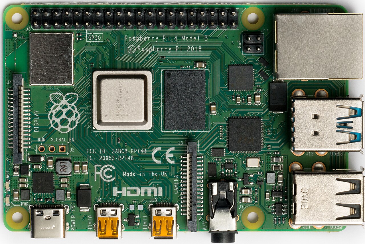
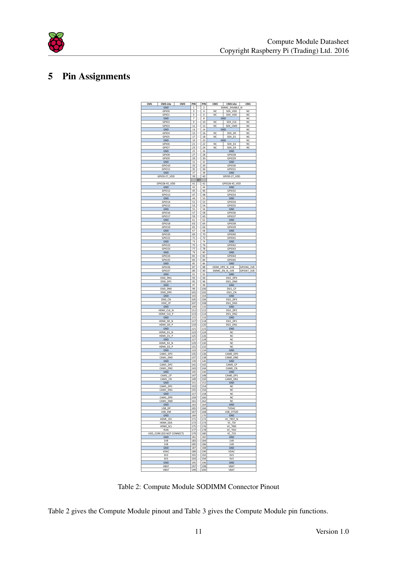
Pinout diagram
| Attr | Specs | verified |
|---|---|---|
soc | Broadcom BCM2837 — quad-core Arm Cortex-A53 (ARMv8-A 64-bit ISA, run with 32-bit userland by default), up to 1.2 GHz, dedicated 512 KB L2 cache; the BCM2837 is an evolution of the BCM2835 (same peripherals, more addressable RAM, quad-core CPU) (datasheet RP-008161-DS §1; official docs compute-module.html). | ? unverified |
gpu | Broadcom VideoCore IV (raspberrypi.com/documentation/computers/compute-module.html model table). | ✔ |
ram | 1 GB LPDDR2 (fixed; the only RAM option) (datasheet §1). | ? unverified |
storage | 4 GB eMMC soldered on CM3 (I/O fixed at 1.8 V, not accessible on module pins); CM3L has none and exposes the SDX pins (datasheet §1, §8). | ? unverified |
connectivity | No Wi-Fi, no Bluetooth, no Ethernet on the module. The peripheral list is: 1× USB 2.0 host/OTG, 1× HDMI 1.3a, composite TV-out, 2× CSI (1 four-lane + 1 two-lane, up to 1 Gbps/lane), 2× DSI (1 four-lane + 1 two-lane), 2× I2C, 2× SPI, 2× UART, 2× SD/SDIO, DPI (24-bit parallel RGB display), SMI (NAND/Intel-mode-80 bus), JTAG (datasheet §2.2, §9). Networking must come from the carrier board (e.g., a USB Ethernet chip such as the LAN9514 spotted on NEC's mezzanine board — community observation in launch-blog comments, not official). | ? unverified |
gpio | 48 usable GPIO lines (GPIO0–45) in two independently powered banks: bank0 = GPIO0–27, bank1 = GPIO28–45. Each bank's VREF supply sets its I/O level anywhere from 1.8 V to 3.3 V; both banks must be powered even if unused. Weak internal pulls (50–65 kΩ) on all but GPIO28/29/44/45; default drive 8 mA, max 16 mA per pin, aggregate ≤ 50 mA per bank. PWM0/PWM1, GPCLK0–2, PCM (I2S) are GPIO alternate functions; no ADC and no DAC on the SoC (datasheet §6, §7, §9.1, Tables 9–10). | ? unverified |
mechanical | 200-pin DDR2-SODIMM form factor (JEDEC MO-224 outline), 67.6 × 31 mm — 1 mm taller than CM1 (datasheet §4; CNX launch article). | ? unverified |
power | six supplies, all mandatory: VBAT (core SMPS input, 2.5–5.0 V, recommended minimum 3500 mW for CM3), 3V3 (≥250 mA), 1V8 (≥250 mA), VDAC (2.5–3.3 V; clean 2.5–2.8 V only if TV-out used, else tie to 3V3), GPIO0-27 VREF and GPIO28-45 VREF (1.8–3.3 V, ≥50 mA), plus SDX VREF on CM3L. Supplies must ramp highest-voltage-first (or simultaneously without crossing) to avoid forward-biasing on-chip diodes / latch-up (datasheet §7, Tables 7–8). | ? unverified |
typical_consumption | ? unverified | |
temperature | nominal operating range −25 °C to +80 °C (limited by eMMC and LPDDR2 parts); DVFS thermal throttling engages when the on-die sensor exceeds 85 °C (datasheet §10). Note: CNX lists −20 to +70 °C for the later CM3+ datasheet — do not mix the two figures. | ? unverified |
- Manufacturer: Raspberry Pi (Trading) Ltd. (now Raspberry Pi Ltd.), United Kingdom.
- Launch: 16 January 2017, announced on the official blog post "Compute Module 3 Launch!" (raspberrypi.com/news/compute-module-3-launch/, fetched 2026-10-13; launch date also confirmed by CNX Software, cnx-software.com/2017-01-16/raspberry-pi-3-compute-modules-cm3-and-cm3l-launched-for-35-and-30/, fetched 2026-10-13).
- Launch price: US$30 for CM3 (4 GB eMMC), US$25 for CM3 Lite (CM3L, no eMMC); the original Compute Module was simultaneously repriced to $25 (official launch blog, same URL). A full development kit (CM3 + Compute Module IO Board V3) sold for about $150 (CNX, same URL).
- Status: End-of-Life. Official EoL date 16 October 2025, due to discontinuation of the core SoC; Raspberry Pi recommends CM3+ for existing designs and CM4S for new SODIMM designs (official docs, raspberrypi.com/documentation/computers/compute-module.html, fetched 2026-10-13; Obsolescence Notice pip.raspberrypi.com/documents/RP-009286-PC). The module had been declared "legacy, not recommended for new designs" since January 2019 (datasheet Release 3, RP-008161-DS).
- Variants: - CM3 — 1 GB LPDDR2 + 4 GB on-module eMMC. - CM3L (CM3 Lite) — same SoC/RAM, no eMMC; the SD/eMMC interface signals (SDX) are exposed on the SODIMM connector so the designer can attach an SD card socket or their own eMMC device (datasheet RP-008161-DS, §1). - A 16 GB-eMMC CM3 variant was produced for NEC's display products (stated by the official NEC_Displays account in the comments of the launch blog; single-source, treat as secondary).
+ Strengths
- System-on-Module in a DDR2 SODIMM socket: the whole Pi 3 computer (SoC, RAM, PMIC, eMMC) in a socketed, mass-production-friendly part with 35 µm hard-gold module edge plating; carrier boards can be simple two-layer designs (datasheet §2.1; launch blog "the module takes care of the complexity of routing out the processor pins…").
- ~10× the CPU performance and 2× the RAM of Compute Module 1, with identical pinout — CM1 designs are largely backward-compatible (launch blog; datasheet §1).
- I/O beyond a normal Pi: 48 GPIO (vs 28 on a Pi board), dual CSI and dual DSI including 4-lane MIPI at 1 Gbps/lane, 24-bit parallel DPI display interface, SMI NAND bus, composite out, JTAG — all on the edge connector (datasheet §2.2).
- Per-bank selectable GPIO voltage (1.8–3.3 V) — level-shifting to 1.8 V peripherals is a carrier-board decision, not a logic-level converter chore (datasheet §7, Table 7).
- USB programming mode: the module can be flashed over USB from any host (including another Pi) without any storage on board — factory-friendly provisioning (datasheet §8).
- Industrial pedigree: long-term availability program (guaranteed to at least January 2026 per datasheet §11), used by NEC in commercial displays (see Projects).
- Not present: wireless (added only from CM4), Ethernet, PCIe, and a field-updatable bootloader EEPROM (CM4+ features) — official docs compute-module.html.
− Weaknesses
- End-of-Life (16 Oct 2025): the BCM2837 was discontinued; no new orders. Migration paths: CM3+ (same footprint, BCM2837B0, better thermals, EOL no earlier than Jan 2028), CM4S (SODIMM, Pi 4 silicon), or CM4/CM5 (new designs). Sources: official docs compute-module.html + Obsolescence Notice RP-009286-PC + datasheet page 1.
- Thermal throttling / hot quad-core: the launch blog explicitly warns the processor "will run much hotter under heavy CPU load, so designers need to consider thermals"; the datasheet documents throttling at 85 °C and warns "the Quad ARM complex in the BCM2837 can generate significant heat output" (launch blog; datasheet §10). CNX notes CM3+ was thermally reworked because CM3 ran hotter under load (CNX CM3+ article).
- CPU clock capped at 1.2 GHz: the silicon can go faster (1.4 GHz on Pi 3B+ boards) but the CM power supply limits it to 1.2 GHz (CNX CM3+ article, same URL).
- Power sequencing trap: ramping supplies in the wrong order can forward-bias on-chip diodes and cause latch-up; all six rails must always be present, even unused ones (datasheet §7, §7.1).
- Reserved 1.8 V pins: HDMI_HPD_N_1V8 and EMMC_EN_N_1V8 are not general GPIO — firmware always expects their special function; reusing them breaks boot/HDMI (datasheet §9.1, bold warning).
- Floating pins at power-on: GPIO28, 29, 44, 45 have no default pull; the datasheet recommends external off-chip pulls so they never float during power-on/initial boot (datasheet §9.1).
- Fixed boot order & slow USB-boot fallback: no EEPROM/BOOT_ORDER; forcing USB boot via EMMC_DISABLE_N costs a couple of seconds of eMMC timeout, and custom carriers need MOSFET circuitry rated for 1.8 V gate switching to automate it (datasheet §8).
- CM1→CM3 upgrade gotchas: module is 1 mm taller and VBAT draws significantly more current — old CM1 carriers with tight z-clearance or weak VBAT regulators can fail (datasheet §1; launch blog).
- Storage ceiling & eMMC wear: only a 4 GB eMMC option (8–32 GB arrived with CM3+); the eMMC I/O rail is hard-wired to 1.8 V (datasheet §1, §7; CNX CM3+ article). >
- No wireless by design: Wi-Fi/Bluetooth require USB add-ons; the SD1 SDIO bus that carries Wi-Fi on a Pi 3B has no radio fitted on CM3 (datasheet §2.2 peripheral list; official docs).
- Stereo-camera sync limitation (affects CM3 camera designs): discussed on the official launch blog between community members and RPi firmware engineer 6by9 — camera modules expose no genlock, sync drift is milliseconds and unfixable in HW (launch blog comments). >
- Retour d'expérience expert expert — expert-raspberrypi
- Petit retour d'experience sur la Compute Module 3 maintenant qu'elle est officiellement en fin de vie. C'etait une super carte pour le design industriel grace au format SODIMM et aux 48 GPIO, mais attention a la gestion thermique. Le quad-core chauffe serieusement en charge lourde et le throttling … — expert-raspberrypi
- Merci pour le rappel. J'ai justement un vieux carrier CM1 que j'essaie d'upgrader. J'ai constate des boot aléatoires jusqu'à ce que je realise que je n'avais pas ajoute les résistances de pull-up externes sur GPIO28, 29, 44 et 45. Le datasheet le dit mais c'est facile a rater quand on migre. Est-ce… — hacker_elec
- Pour le boot USB, sans le MOSFET ca reste manuel et lent avec le timeout eMMC. Le vrai souci reste l'absence totale de Wi-Fi et Bluetooth sur le module. Il faut obligatoirement un dongle USB ou un module externe sur le carrier, ce qui prend la place du port unique USB 2.0. Si ton projet a besoin de… — maker_pragmatique
Community feedback and projects
- Compute Module 3 – RASPBERRY PI forum.digikey.com
- Empfehlungen zum Compute Module 3 von RASPBERRY PI (π) forum.digikey.com
- How to boot Android Things 0.6.1 DevPreview in CM3L (Computer Module 3 Lite) stackoverflow.com
- Using Raspberry Pi Display on CM3 with Android Things stackoverflow.com
Content not available yet.
- pip.raspberrypi.com/documents/RP-008161-DS
- pip.raspberrypi.com/documents/RP-008164-DS
- pip.raspberrypi.com/documents/RP-008256-DS
- pip.raspberrypi.com/documents/RP-009286-PC
- pip.raspberrypi.com/documents/RP-003469-WP
- raspberrypi.com/documentation/computers/compute-module.html
- github.com/raspberrypi/documentation
- raspberrypi.com/news/compute-module-3-launch/
- raspberrypi.com/news/compute-module-3-on-sale-now-from-25/
- github.com/raspberrypi/usbboot
- forums.raspberrypi.com
- launch
- CM3+
- CutiePi
- en.wikipedia.org/wiki/Raspberry_Pi#Compute_Module_series
- End-of-Life (16 Oct 2025): the BCM2837 was discontinued; no new orders. Migration paths: CM3+ (same footprint, BCM2837B0, better thermals, EOL no earlier than Jan 2028), CM4S (SODIMM, Pi 4 silicon), or CM4/CM5 (new designs). Sources: official docs compute-module.html + Obsolescence Notice RP-009286-PC + datasheet page 1.
- Thermal throttling / hot quad-core: the launch blog explicitly warns the processor "will run much hotter under heavy CPU load, so designers need to consider thermals"; the datasheet documents throttling at 85 °C and warns "the Quad ARM complex in the BCM2837 can generate significant heat output" (launch blog; datasheet §10). CNX notes CM3+ was thermally reworked because CM3 ran hotter under load (CNX CM3+ article).
- CPU clock capped at 1.2 GHz: the silicon can go faster (1.4 GHz on Pi 3B+ boards) but the CM power supply limits it to 1.2 GHz (CNX CM3+ article, same URL).
- Power sequencing trap: ramping supplies in the wrong order can forward-bias on-chip diodes and cause latch-up; all six rails must always be present, even unused ones (datasheet §7, §7.1).
- Reserved 1.8 V pins: HDMI_HPD_N_1V8 and EMMC_EN_N_1V8 are not general GPIO — firmware always expects their special function; reusing them breaks boot/HDMI (datasheet §9.1, bold warning).
- Floating pins at power-on: GPIO28, 29, 44, 45 have no default pull; the datasheet recommends external off-chip pulls so they never float during power-on/initial boot (datasheet §9.1).
- Fixed boot order & slow USB-boot fallback: no EEPROM/BOOT_ORDER; forcing USB boot via EMMC_DISABLE_N costs a couple of seconds of eMMC timeout, and custom carriers need MOSFET circuitry rated for 1.8 V gate switching to automate it (datasheet §8).
- CM1→CM3 upgrade gotchas: module is 1 mm taller and VBAT draws significantly more current — old CM1 carriers with tight z-clearance or weak VBAT regulators can fail (datasheet §1; launch blog).
- Storage ceiling & eMMC wear: only a 4 GB eMMC option (8–32 GB arrived with CM3+); the eMMC I/O rail is hard-wired to 1.8 V (datasheet §1, §7; CNX CM3+ article). >
- No wireless by design: Wi-Fi/Bluetooth require USB add-ons; the SD1 SDIO bus that carries Wi-Fi on a Pi 3B has no radio fitted on CM3 (datasheet §2.2 peripheral list; official docs).
- Stereo-camera sync limitation (affects CM3 camera designs): discussed on the official launch blog between community members and RPi firmware engineer 6by9 — camera modules expose no genlock, sync drift is milliseconds and unfixable in HW (launch blog comments). >
- Premier démarrage d'un Compute Module 3 sur la carte CMIO3 debutant Schéma : un module CM3 inséré dans le connecteur SODIMM 200 broches de la carte Compute Module IO Board V3 (CMIO3), avec carte microSD, câble micro-USB d'alimentation et câble HDMI.
- Faire clignoter une LED sur les GPIO du CM3 debutant Schéma : module CM3 sur carte CMIO3, une LED avec résistance de 330 Ω branchée entre la broche GPIO17 du connecteur GPIO et la masse (GND).
- Allumer une LED avec un bouton poussoir sur le CM3 debutant Schéma : bouton poussoir entre GPIO4 et GND, LED avec résistance 330 Ω entre GPIO17 et GND, les deux reliés à la carte CMIO3 portant un module CM3.
- Flasher l'eMMC d'un CM3 par USB avec rpiboot intermediaire Schéma : un PC hôte relié en micro-USB au port device de la carte CMIO3, un module CM3 inséré, le cavalier EMMC_DISABLE_N posé ; le module apparaît comme disque USB.
- Lire un capteur BME280 en I2C sur le CM3 intermediaire Schéma : capteur BME280 relié au bus I2C1 du CM3 sur carte CMIO3 — SDA sur GPIO2, SCL sur GPIO3, VCC 3,3 V, GND.
- Brancher une caméra CSI (OV5647) sur un CM3 intermediaire Schéma : caméra Raspberry Pi v2 (IMX219) reliée par nappe CSI au connecteur CSI principal de la carte CMIO3 portant un module CM3 ; le second connecteur CSI 2 voies est visible à côté.
- Vision stéréo : deux caméras CSI sur un CM3 avance Schéma : deux caméras Raspberry Pi reliées aux deux connecteurs CSI du CM3 sur carte CMIO3 — CSI 4 voies (caméra gauche) et CSI 2 voies (caméra droite) — avec la note « pas de genlock : dérive de quelques millisecondes ».
- Piloter un écran parallèle 24 bits en DPI sur le CM3 avance Schéma : dalle LCD à interface parallèle RGB 24 bits reliée au bus DPI 24 bits du connecteur SODIMM d'un CM3 sur carte porteuse custom, avec les signaux R0-R7, G0-G7, B0-B5, PCLK, HSYNC, VSYNC, DE.
- Concevoir le séquenceur d'alimentation d'une carte porteuse CM3 avance Schéma : carte porteuse custom avec les six rails d'alimentation obligatoires du CM3 — VBAT (2,5-5,0 V), 3V3, 1V8, VDAC, VREF bank0, VREF bank1 — et l'ordre de rampe du plus haut voltage vers le plus bas pour éviter le latch-up.
Code library — examples written for this board
clignotante.pyPythonbouton-gpio.pyPythoncapteur-i2c.shBashsurveillance-temperature.shBashcapteur-dht11.pyPythonservo-pwm-sysfs.shBashserveur-web-capteur.pyPythonwifi-station.shBashjournal-cron.shBashveilleur-systemd.pyPython
Examples and repos found online
- raspberrypi/usbboot github.com
- raspberrypi/linux github.com
- raspberrypi/noobs github.com
- joan2937/pigpio github.com