BeagleBone Black (TI Sitara AM3358)
⚡ The essentials in 60 seconds
- soc — TI Sitara AM3358BZCZ100 ("CZ" = Cortex-A8 + SGX530 + PRU, 100 = 1 GHz speed grade), 2000 MIPS (SRM ch. 4). CPU: 1× ARM Cortex-A8 (ARMv7-A, single core), OPPs at 275/500/600/800/1000 MHz (SRM ch. 6 processor table; OPP table in am33xx.dtsi). L1 64 KB + L2 256 KB cache, 128 KB other on-chip RAM, 64-channel EDMA (SRM ch. 6).
- co_processors — 2× PRU-ICSS Programmable Real-Time Units, 32-bit load/store RISC @ 200 MHz, 8 KB instruction RAM + 8 KB data RAM per core + 12 KB shared RAM, parity-protected, fast I/O, 16 in / 16 out pins per core (not all reachable on the BBB) (SRM ch. 6 "PRU-ICSS").
- gpu — Imagination PowerVR SGX530 @ 200 MHz, ~20 M polygons/s (SRM ch. 4; Wikipedia).
- ram — 512 MB DDR3L (single x16 device: Micron MT41K256M16HA-125 or Kingston D2516EC4BXGGB), 400 MHz clock = 800 MT/s ≈ 1.6 GB/s (SRM ch. 5).
- storage — 4 GB 8-bit eMMC (Rev C+; 2 GB on Rev A/B) on MMC1/GPMC pins + microSD (MMC0, 4-bit only — 8-bit lines collide with the Ethernet pins) (SRM ch. 5). 4 KB board-identity EEPROM on I2C0 (atmel,24c32 in mainline DTS).
- networking — 10/100 Ethernet only (SMSC PHY, MII via the AM335x CPSW switch, phy-mode = "mii" in am335x-bone-common.dtsi). No Wi-Fi / Bluetooth on the stock board (use the Wireless variant or a USB dongle).
- On this board : 9 tutorials · 10 code
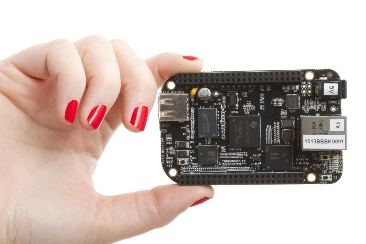
The BeagleBone Black stands as a cornerstone in the world of single-board computers, representing a unique intersection of affordability, industrial-grade reliability, and deep hardware accessibility. Introduced in April 2013 by the BeagleBoard.org Foundation, a non-profit organization based in Michigan, this board was designed to provide developers with a low-cost platform that did not compromise on expandability or real-time capabilities. While it launched with a manufacturer’s suggested retail price of forty-five US dollars, its value proposition has extended far beyond its initial cost, maintaining active production and support for over a decade. This longevity is a testament to its robust design and the strong community support that surrounds it, making it a staple for both educational institutions and industrial applications where long-term availability is critical.
At the heart of the BeagleBone Black lies the Texas Instruments Sitara AM3358 System-on-Chip. This processor features a single ARM Cortex-A8 core, a 32-bit architecture that operates at speeds up to one gigahertz. For those new to embedded systems, it is important to understand that while a single core may seem limiting compared to modern multi-core desktop processors, the Cortex-A8 is highly efficient and sufficient for controlling hardware, running lightweight Linux distributions, and handling network tasks. The system is supported by 512 megabytes of DDR3L RAM, which provides enough memory to run a full operating system like Debian Linux, which ships pre-installed on newer revisions. Storage is handled by an embedded MultiMediaCard, or eMMC, with capacities of four gigabytes on current models. Unlike removable SD cards, eMMC is soldered directly to the board, offering faster and more deterministic boot times, which is crucial for industrial devices that must start up reliably every time power is applied.
What truly distinguishes the BeagleBone Black from many of its competitors, such as the Raspberry Pi, is the inclusion of two Programmable Real-Time Units, or PRUs. These are specialized 32-bit co-processors running at 200 megahertz that operate independently of the main Linux operating system. In practical terms, this means the PRUs can handle time-critical tasks, such as reading sensors at precise microsecond intervals or controlling motors, without being interrupted by the delays inherent in a general-purpose operating system. This capability allows the BeagleBone Black to function as a deterministic controller, bridging the gap between simple hobbyist boards and expensive industrial programmable logic controllers. The PRUs are accessible through a dedicated toolchain and can be programmed in assembly or C, offering a level of hardware control that is rarely found on consumer-grade development boards.
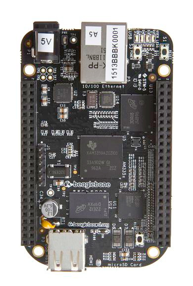
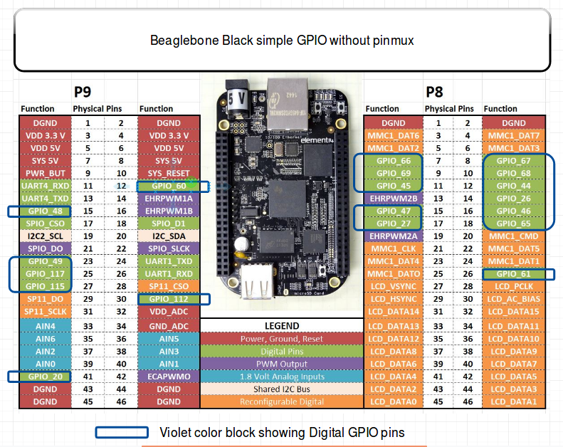
The board’s connectivity and expansion capabilities are equally impressive. It features two forty-six-pin expansion headers, known as P8 and P9, which expose a vast array of input and output options. These headers provide access to up to sixty-nine general-purpose input-output pins, seven analog inputs, four universal asynchronous receiver-transmitter ports, two inter-integrated circuit buses, and two serial peripheral interface buses. The analog inputs are particularly noteworthy but require careful attention; they operate at a maximum of 1.8 volts, which is significantly lower than the 3.3-volt logic levels of the digital pins. Connecting a 3.3-volt signal directly to an analog input pin can damage the processor, so users must employ voltage dividers or level shifters when interfacing with external sensors. The digital pins themselves are also strictly 3.3-volt logic, and applying 5-volt signals to them will cause permanent damage. This strict voltage discipline is a key learning point for developers transitioning from other platforms or working with mixed-voltage systems.
For networking and media, the BeagleBone Black includes a 10/100 megabit Ethernet port, which is sufficient for most control and data logging applications but may feel slow for high-bandwidth tasks. It also features a micro-HDMI port capable of outputting video up to 1280 by 1024 resolution, along with stereo audio. However, the video output is limited to 24 hertz at 1080p resolution, making it unsuitable for smooth video playback or desktop use. The board is powered via a micro-USB connector or a barrel jack, with a power management integrated circuit that handles switching between power sources. Developers should be aware that when powered via USB, the board provides limited current, which may not be enough to power multiple high-demand peripherals or capes, necessitating the use of the barrel jack for more demanding setups.
The ecosystem surrounding the BeagleBone Black is defined by its "capes," which are add-on boards that stack onto the expansion headers. The board supports up to four stacked capes, and each cape can contain an identification EEPROM that allows the software to automatically configure the necessary pin multiplexing. This plug-and-play approach simplifies the addition of complex peripherals, such as motor drivers, wireless modules, or industrial interfaces like CAN bus, which is natively supported by the SoC. The open-source nature of the hardware design means that schematics and PCB layouts are publicly available, encouraging a culture of transparency and customization. This openness has led to a wide variety of community-created capes and derivatives, including wireless variants and industrial versions with extended temperature ranges.
Despite its strengths, the BeagleBone Black has limitations that users must consider. The single-core processor and 512 megabytes of RAM make it unsuitable for heavy computational tasks or running modern desktop environments. The 10/100 Ethernet port is a bottleneck for data-intensive applications, and the lack of built-in Wi-Fi or Bluetooth requires external dongles or the use of the specific Wireless variant. Furthermore, the boot process involves specific nuances, such as holding the boot button to force booting from an SD card instead of the internal eMMC, a detail that can confuse new users. The hardware revisions have addressed several early production issues, such as boot failures and HDMI jitter, highlighting the iterative nature of its development. Nevertheless, for applications requiring precise real-time control, extensive I/O, and long-term stability, the BeagleBone Black remains a powerful and pedagogically rich platform that teaches fundamental concepts of embedded systems engineering.
Pinout diagram
| Attr | Specs | verified |
|---|---|---|
soc | TI Sitara AM3358BZCZ100 ("CZ" = Cortex-A8 + SGX530 + PRU, 100 = 1 GHz speed grade), 2000 MIPS (SRM ch. 4). CPU: 1× ARM Cortex-A8 (ARMv7-A, single core), OPPs at 275/500/600/800/1000 MHz (SRM ch. 6 processor table; OPP table in am33xx.dtsi). L1 64 KB + L2 256 KB cache, 128 KB other on-chip RAM, 64-channel EDMA (SRM ch. 6). | ✔ |
co_processors | 2× PRU-ICSS Programmable Real-Time Units, 32-bit load/store RISC @ 200 MHz, 8 KB instruction RAM + 8 KB data RAM per core + 12 KB shared RAM, parity-protected, fast I/O, 16 in / 16 out pins per core (not all reachable on the BBB) (SRM ch. 6 "PRU-ICSS"). | ✔ |
gpu | Imagination PowerVR SGX530 @ 200 MHz, ~20 M polygons/s (SRM ch. 4; Wikipedia). | ✔ |
ram | 512 MB DDR3L (single x16 device: Micron MT41K256M16HA-125 or Kingston D2516EC4BXGGB), 400 MHz clock = 800 MT/s ≈ 1.6 GB/s (SRM ch. 5). | ✔ |
storage | 4 GB 8-bit eMMC (Rev C+; 2 GB on Rev A/B) on MMC1/GPMC pins + microSD (MMC0, 4-bit only — 8-bit lines collide with the Ethernet pins) (SRM ch. 5). 4 KB board-identity EEPROM on I2C0 (atmel,24c32 in mainline DTS). | ✔ |
networking | 10/100 Ethernet only (SMSC PHY, MII via the AM335x CPSW switch, phy-mode = "mii" in am335x-bone-common.dtsi). No Wi-Fi / Bluetooth on the stock board (use the Wireless variant or a USB dongle). | ✔ |
usb | 1× USB2.0 HS host Type-A (≤500 mA, LS/FS/HS) + 1× mini-USB client (USB0, powers the board) (SRM ch. 4). | ✔ |
video_audio | micro-HDMI via a 16-bit HDMI framer (TDA19988-class): max 1280×1024, 1920×1080@24 Hz with EDID; stereo audio over HDMI (needs the framer's 24.576 MHz clock, see Problems) (SRM ch. 4). | ✔ |
gpio_expansion | 2× 46-pin headers (P8, P9) = 92 pins, all 3.3 V I/O (5 V on power pins only). Up to 69 GPIO, 7 analog inputs, 4 UARTs, 2× I2C, 2× SPI, 2× CAN, 8× PWM (eHRPWM/eCAP), eQEP, McASP0, LCD/GPMC/MMC1/MMC2 muxed, XDMA interrupt, power-button line, up to 4 stacked capes with per-cape ID EEPROMs (I2C2 addresses 0x54–0x57 in mainline DTS) (SRM ch. 4/ch. 7; Adafruit — Setting up IO Python Library on BeagleBone Black: "7 Analog Pins, 65 Digital Pins at 3.3V, 2x I2C, 2x SPI, 2x CAN Bus, 4x UART, 8x PWM"). | ✔ |
adc | 8-channel 12-bit ADC; analog I/O supply is 1.8 V (VDD_ADC) — absolute max on AIN pins is 1.8 V (SRM ch. 4 "AIN (1.8V MAX)", ch. 6 "IO Supply (V): 1.8V(ADC), 3.3V"). Broken-out channels (P9): AIN0=P9_39, AIN1=P9_40, AIN2=P9_37, AIN3=P9_38, AIN4=P9_33, AIN5=P9_36, AIN6=P9_35, VADC(1.8 V out)=P9_32, AGND=P9_34 (SRM ch. 7 P9 table). | ✔ |
power | 5 V via micro-USB client (≤500 mA) or 5.5/2.1 mm center-positive barrel jack (≥1 A typical); TPS65217C PMIC auto-selects, hot-switching USB→DC; the board can also be powered from the 5 V pins of the headers. Measured draw @5 V (HDMI monitor + hub + 4 GB stick + 100M Ethernet attached): U-Boot idle 210 mA, kernel-boot peak 460 mA, kernel idle 350 mA, page load 430 mA (SRM ch. 6 "Power Consumption"). Battery-charger pads (BAT/SENSE/TS/GND) for Li-ion experiments; power button on the PMIC. | ✔ |
crypto | AES and SHA accelerators enabled in mainline (&aes/&sham "okay" in am335x-bone-common.dtsi). | ✔ |
mechanical_thermal | 86.36 × 53.34 mm (3.5" × 2.15"), 6-layer PCB, 39.68 g (SRM ch. 4/ch. 9). | ✔ |
- Manufacturer / steward: Designed for the BeagleBoard.org Foundation (Michigan, USA 501(c)(3) non-profit). The board was designed by Gerald Coley of EmProDesign; PCB layout through revision B was done by Circuitco (sole funder of the original build), later PCB revisions by Embest (Avent subsidiary); manufactured and warranted by BeagleBoard.org partners (BBB System Reference Manual, ch. 4 "Overview", retrieved 2026-10-13).
- Year introduced: 2013-04-23 (initial production rev A5A; document rev A5.2 dated the same day) (Wikipedia — BeagleBoard family table, System Reference Manual ch. 2 Change History, both retrieved 2026-10-13).
- Launch price: US$45 — Wikipedia's PocketBeagle comparison records the BBB MSRP as "US$45 for BeagleBone Black" (Dec 2018), the price the board launched with and held for years (Wikipedia — BeagleBoard, retrieved 2026-10-13).
- Status: Active / still sold. Listed on the official product page beagleboard.org/boards/beaglebone-black (fetched live 2026-10-13: "low-cost, high-expansion, community-supported development platform"). It is a 13-year-old design kept in production for industrial/education customers; the Foundation's newer boards (PocketBeagle, BeaglePlay, BeagleBone AI-64) sit alongside it.
- Hardware revisions (all from the official Change History, ch. 2, retrieved 2026-10-13): - Rev A5A (Jan 2013): initial production, 2 GB eMMC, Ångström Linux preinstalled. - Rev A5B: LEDs dimmed (820 Ω → 4.75 kΩ); Rev A5C: HDMI jitter fix (R45–R48). - Rev A6 / A6A: SYS_RESETn glitch fix (ORed with PORZn); C25 cap fix for a "won't boot 1 in 20 tries" issue. - Rev B: processor changed to AM3358BZCZ100 (1 GHz grade). - Rev C (2014-03-21): eMMC 2 GB → 4 GB (2 GB parts being phased out); ships Debian. - Rev C1/C2: DDR3/eMMC supplier swaps (Micron ↔ Kingston). - Rev C3 (2021): Ethernet-PHY reset on GPIO1_8 (fixes a start-up issue, git.beagleboard.org issue #4), new microSD card cage (issue #6); Rev C3a: USB Type-A host connector.
- Variants: BeagleBone Black Wireless (Octavo OSD3358 SiP + Wi-Fi b/g/n + BT 4.1 LE, mainline am335x-boneblack-wireless.dts), BeagleBone Black Industrial (extended-temp variant, referenced by CNX Software), Seeed BeagleBone Green / Green Wireless, and the PocketBeagle family built on the same silicon (Wikipedia, retrieved 2026-10-13).
+ Strengths
- PRU-ICSS — the unique selling point vs any Raspberry Pi. Two user-programmable 200 MHz 32-bit cores wired directly to the I/O ring, giving deterministic, OS-bypassing bit-banging, motor control, industrial fieldbuses and sampling while Linux runs normally (SRM ch. 6). Google Research built PRUDAQ, a 40 MSPS data-acquisition cape on the PRUs (github.com/google/prudaq, retrieved 2026-10-13). No Pi model exposes user-programmable real-time I/O cores like this.
- Cape ecosystem: 2×46 headers, mechanical keying around the Ethernet jack, 4-deep stacking, per-cape ID EEPROMs (0x54–0x57) so software can auto-configure pin muxes — the mechanism that made the BBB's device-tree-overlay capemanager possible (SRM ch. 8 "Cape Board Support").
- eMMC as boot device: x8-wide, deterministic vs a microSD card (the manual explicitly cites "performance boost due to deterministic properties vs. microSD") (SRM ch. 4).
- Real-time / industrial peripherals: 2× CAN, eHRPWM with high-res period, 3× eCAP, 3× eQEP (encoders), McASP0 audio, 12-bit ADC, XDMA interrupt to the PRUs (SRM ch. 4/ch. 6).
- Power engineering: PMIC reports whether USB or DC is feeding the board (read over I²C), power-button graceful shutdown, battery-charger test pads, RTC rail (SRM ch. 6).
- Open hardware: full schematics/PCB files public at openbeagle.org/beagleboard/beaglebone-black (linked from the official docs page, retrieved 2026-10-13).
- HDMI audio + video on a $45 board (max 1280×1024 / 1080p24) with a 6-pin 3.3 V TTL debug serial header — no USB-serial chip needed (SRM ch. 4).
− Weaknesses
- ADC inputs are 1.8 V max — not 3.3 V. Feeding 3.3 V (or 5 V) into an AIN pin damages the SoC; the analog supply VDD_ADC (P9_32) is 1.8 V and AGND (P9_34) must be referenced properly (SRM ch. 4 "AIN (1.8V MAX)"). This surprises everyone coming from the Pi's external-ADC assumption or the 3.3 V logic levels.
- 5 V logic kills the headers: "Do not connect 5V logic level signals to these pins or the board will be damaged", and never apply voltage to I/O pins while the board is unpowered — back-powering through ESD diodes damages the processor and voids warranty (SRM ch. 7).
- Power-over-USB traps: USB gives ≤500 mA while kernel-boot peaks at 460 mA before any load; when powered from USB the VDD_5V rail is absent on the headers (only PMIC-derived SYS_5V), so 5 V-hungry capes silently misbehave; the docs recommend external 5 V for capes/USB-host loads (SRM ch. 6 "USB Power").
- RTC-only power-off mode can damage the board: the TPS65217 "SLEEP" state was found to risk hardware damage on most BeagleBone revisions; mainline ships ti,pmic-shutdown-controller so poweroff forces OFF-state instead, with a long explanatory comment and linux-omap thread links (am335x-bone-common.dtsi TPS comment, spinics msg118585).
- SYSBOOT pins are on P8: P8_27…P8_46 (the LCD bus) are the AM335x SYSBOOT/boot-mode pins and the HDMI framer's inputs; driving them from a cape before SYS_RESETn rises can change the boot order and the board won't boot. The framer also can't be powered off (it would be back-powered through its input pins) (SRM ch. 8).
- eMMC steals 10 header pins: the eMMC hangs off the GPMC/MMC1 pins shared with P8; using those pins requires holding the eMMC in reset, and the GPMC bus is "not accessible in some cases" because of it (SRM ch. 4/ch. 8).
- P9_22 / GPIO3_21 carries the 24.576 MHz HDMI-audio clock: it is a clock input to the SoC; to reuse that pin as GPIO you must disable the clock (killing HDMI audio) (SRM ch. 4).
- 1 GHz is a speed-grade promise, not a guarantee for early silicon: mainline enables the 1 GHz "Nitro" OPP for this board with the comment "All PG 2.0 silicon may not support 1GHz but some of the early BeagleBone Blacks have PG 2.0 silicon which is guaranteed to support 1GHz" (am335x-boneblack.dts).
- Boot-device gotchas: RESET does not re-select the boot device (hold BOOT while cycling power); a broken eMMC image with valid ROM headers keeps the ROM committed to MMC1 — the boot button is the escape hatch (SRM ch. 5).
- Production-revision bugs fixed late: SYS_RESETn glitch (Rev A6), 1-in-20 boot failures (Rev A6A, C25), HDMI jitter (Rev A5C), Ethernet-PHY start-up issue needing a GPIO reset added in Rev C3 (SRM ch. 2, issue #4).
- PRU toolchain historically unsupported by TI on this platform: the System Reference Manual states flatly "This feature is not supported by Texas Instruments" and points to the community am335x_pru_package (SRM ch. 6); today a mainline remoteproc driver exists (drivers/remoteproc/pru_rproc.c), but PRU docs/tooling remain fragmented across TI SDK, community packages and mainline.
- Desktop-use limits: 10/100 Ethernet, 512 MB RAM, single core, 1080p only at 24 Hz — fine as an I/O controller, poor as a mini-PC.
- Retour d'expérience expert expert — expert-pi-like
- Je tourne sur la BBB depuis pas mal de temps et je confirme les points forts : les deux coeurs PRU sont vraiment uniques pour le controle temps reel, et l'ecosysteme de capes avec les EEPROMs d'ID simplifie enormement la vie. Par contre, attention aux pieges documentes. Le plus classique est l'ADC … — expert-pi-like
- Merci pour le rappel sur l'ADC, je l'ai lu dans la doc mais j'ai failli faire l'erreur en connectant un capteur analogique. Petite question sur l'alimentation : je compte alimenter la carte par USB pour un petit projet domotique. Si je branche une cape qui demande un peu plus de courant, est-ce que… — maker_nouveau
- @maker_nouveau L'USB te donne seulement 500mA max, or le boot seul consomme deja 460mA. Si ta cape tire dessus, tu vas avoir des coupures instables ou le port qui coupe. Le vrai piege c'est que le rail 5V officiel n'est pas sur les pins headers quand tu es en USB (seule la tension derivee du PMIC e… — hacker_labs
Community feedback and projects
- BeagleBone Black: Recommended image for remote devices in field. forum.beagleboard.org
- 4DCape LCD on BeagleBone Black Debian 13.5 2026-05-19 IoT (v6.18.x) forum.beagleboard.org
- Enable SPI BeagleBone Black Yocto (kirkstone) forum.beagleboard.org
- docs.beagleboard.org — BeagleBone Black
- beaglebone-black.pdf
- beagleboard.org/boards/beaglebone-black
- openbeagle.org/beagleboard/beaglebone-black
- github.com/beagleboard/beaglebone-black
- ti.com/product/am3358
- ti.com/product/TPS65217C
- am335x-boneblack.dts
- am335x-bone-common.dtsi
- drivers/remoteproc/pru_rproc.c
- github.com/beagleboard/am335x_pru_package
- github.com/google/prudaq
- github.com/RobertCNelson/bb-kernel
- IO Python
- Device Tree intro
- WiFi setup
- forum.beagleboard.org/tag/beaglebone-black
- Wikipedia — BeagleBoard
- ADC inputs are 1.8 V max — not 3.3 V. Feeding 3.3 V (or 5 V) into an AIN pin damages the SoC; the analog supply VDD_ADC (P9_32) is 1.8 V and AGND (P9_34) must be referenced properly (SRM ch. 4 "AIN (1.8V MAX)"). This surprises everyone coming from the Pi's external-ADC assumption or the 3.3 V logic levels.
- 5 V logic kills the headers: "Do not connect 5V logic level signals to these pins or the board will be damaged", and never apply voltage to I/O pins while the board is unpowered — back-powering through ESD diodes damages the processor and voids warranty (SRM ch. 7).
- Power-over-USB traps: USB gives ≤500 mA while kernel-boot peaks at 460 mA before any load; when powered from USB the VDD_5V rail is absent on the headers (only PMIC-derived SYS_5V), so 5 V-hungry capes silently misbehave; the docs recommend external 5 V for capes/USB-host loads (SRM ch. 6 "USB Power").
- RTC-only power-off mode can damage the board: the TPS65217 "SLEEP" state was found to risk hardware damage on most BeagleBone revisions; mainline ships ti,pmic-shutdown-controller so poweroff forces OFF-state instead, with a long explanatory comment and linux-omap thread links (am335x-bone-common.dtsi TPS comment, spinics msg118585).
- SYSBOOT pins are on P8: P8_27…P8_46 (the LCD bus) are the AM335x SYSBOOT/boot-mode pins and the HDMI framer's inputs; driving them from a cape before SYS_RESETn rises can change the boot order and the board won't boot. The framer also can't be powered off (it would be back-powered through its input pins) (SRM ch. 8).
- eMMC steals 10 header pins: the eMMC hangs off the GPMC/MMC1 pins shared with P8; using those pins requires holding the eMMC in reset, and the GPMC bus is "not accessible in some cases" because of it (SRM ch. 4/ch. 8).
- P9_22 / GPIO3_21 carries the 24.576 MHz HDMI-audio clock: it is a clock input to the SoC; to reuse that pin as GPIO you must disable the clock (killing HDMI audio) (SRM ch. 4).
- 1 GHz is a speed-grade promise, not a guarantee for early silicon: mainline enables the 1 GHz "Nitro" OPP for this board with the comment "All PG 2.0 silicon may not support 1GHz but some of the early BeagleBone Blacks have PG 2.0 silicon which is guaranteed to support 1GHz" (am335x-boneblack.dts).
- Boot-device gotchas: RESET does not re-select the boot device (hold BOOT while cycling power); a broken eMMC image with valid ROM headers keeps the ROM committed to MMC1 — the boot button is the escape hatch (SRM ch. 5).
- Production-revision bugs fixed late: SYS_RESETn glitch (Rev A6), 1-in-20 boot failures (Rev A6A, C25), HDMI jitter (Rev A5C), Ethernet-PHY start-up issue needing a GPIO reset added in Rev C3 (SRM ch. 2, issue #4).
- PRU toolchain historically unsupported by TI on this platform: the System Reference Manual states flatly "This feature is not supported by Texas Instruments" and points to the community am335x_pru_package (SRM ch. 6); today a mainline remoteproc driver exists (drivers/remoteproc/pru_rproc.c), but PRU docs/tooling remain fragmented across TI SDK, community packages and mainline.
- Desktop-use limits: 10/100 Ethernet, 512 MB RAM, single core, 1080p only at 24 Hz — fine as an I/O controller, poor as a mini-PC.
- Premier boot de la BeagleBone Black avec un seul câble mini-USB debutant Schéma : IMG-beaglebone-black-debutant-1-premier-boot-cable-mini-usb.svg — BeagleBone Black reliée à un PC par un câble mini-USB, fenêtre affichant start.htm sur le lecteur USB virtuel, bouton BOOT et jack d'alimentation annotés.
- Comprendre les triggers en pilotant les 4 LED utilisateur debutant Schéma : IMG-beaglebone-black-debutant-2-leds-user-sysfs-triggers.svg — BeagleBone Black vue de dessus avec les 4 LED utilisateur (heartbeat, mmc0, usr2, usr3) surlignées près du connecteur Ethernet, liste des triggers sysfs en médaillon.
- Bouton et LED avec Adafruit_BBIO, la bibliothèque historique debutant Schéma : IMG-beaglebone-black-debutant-3-bouton-led-adafruit-bbio.svg — breadboard avec BeagleBone Black : bouton entre P9_11 et GND, LED + 330 Ω sur P8_11, broches P8 et P9 repérées sur la carte.
- Lire l'ADC 12 bits sans griller le SoC : la règle des 1,8 V intermediaire Schéma : IMG-beaglebone-black-intermediaire-1-adc-1-8v-lecture-iio.svg — pont diviseur de résistance sur la BeagleBone Black : signal 3,3 V entrant, deux résistances, point milieu vers P9_33 (AIN4), P9_32 VDD_ADC 1,8 V et P9_34 AGND repérés, badge « 1,8 V MAX ».
- Ajouter une horloge temps réel sur le bus I2C des capes intermediaire Schéma : IMG-beaglebone-black-intermediaire-2-horloge-rtc-i2c-bus-cape.svg — module RTC DS3231 avec pile bouton câblé sur P9_19 (SDA) et P9_20 (SCL) + 3,3 V/GND de la BeagleBone Black, bus I2C2 partagé avec les EEPROM de capes (0x54-0x57) en médaillon.
- Micro-HDMI : exploiter les limites d'affichage de la BBB intermediaire Schéma : IMG-beaglebone-black-intermediaire-3-micro-hdmi-limites-affichage.svg — BeagleBone Black reliée en micro-HDMI à un moniteur, badges « 1280×1024 max » et « 1920×1080 à 24 Hz seulement », broche P9_22 (horloge audio 24,576 MHz) surlignée en avertissement.
- Capes historiques : capemanager, EEPROM d'identification et pièges des broches avance Schéma : IMG-beaglebone-black-avance-1-capes-legacy-capemanager-eeprom.svg — pile de 4 capes empilées sur les nappes P8/P9 d'une BeagleBone Black, EEPROM I2C 0x54-0x57 en médaillon, zone P8_27 à P8_46 barrée en rouge avec mention « broches SYSBOOT — ne pas piloter ».
- Programmer les cores PRU : le clignotement temps réel déterministe avance Schéma : IMG-beaglebone-black-avance-2-pru-blink-cores-temps-reel.svg — schéma bloc du PRU-ICSS de l'AM335x (2 cores 200 MHz, 8 Ko de mémoire d'instructions chacun, RAM partagée 12 Ko) relié directement aux broches d'entrée-sortie, Linux tournant à côté sans y toucher.
- Bus CAN : exploiter les deux contrôleurs DCAN avec can-utils avance Schéma : IMG-beaglebone-black-avance-3-bus-can-dcan-candump.svg — deux BeagleBone Black reliées par un bus CAN différentiel (CAN_H, CAN_L, résistance de terminaison 120 Ω de chaque côté), transceivers SN65HVD230 sur les broches P8_17/P8_18.
Code library — examples written for this board
clignotante.pyPythonbouton-gpio.pyPythoncapteur-i2c.shBashsurveillance-temperature.shBashcapteur-dht11.pyPythonservo-pwm-sysfs.shBashserveur-web-capteur.pyPythonreseau-ethernet.shBashjournal-cron.shBashveilleur-systemd.pyPython
Examples and repos found online
- beagleboard/beaglebone-getting-started github.com
- adafruit/adafruit-beaglebone-io-python github.com
- RobertCNelson/bb.org-overlays github.com
- RobertCNelson/linux-dev github.com